
Testing method of an IC card including a ZigBee device

a testing method and zigbee technology, applied in the field of testing methods of ic cards including zigbee devices, can solve the problems of zigbee controllers that cannot directly identify and return the identification code of defective zigbee devices, and the zigbee controllers that are typically not able to identify

Active Publication Date: 2012-02-28
STMICROELECTRONICS INT NV
View PDF5 Cites 0 Cited by
  • Summary
  • Abstract
  • Description
  • Claims
  • Application Information

AI Technical Summary

Benefits of technology

This approach allows for rapid and efficient testing of ZigBee devices without significantly increasing the time for checking the IC Card's overall hardware and software resources, enabling quick identification and selection of defective IC Cards by returning a list of associated Identifiers.

Problems solved by technology

A problem of such a method for testing is that checking the ZigBee device takes much more time than checking the IC device.
Another problem of such a method for testing is that the ZigBee Controller typically cannot directly identify and return an identification code of a defective ZigBee device.
Since a defective ZigBee device is typically unable to connect and transmit over the ZigBee network, for example, due to a broken antenna 7, the ZigBee Controller typically cannot identify it.
It is typically not possible to identify the corresponding ZigBee device when it is unable to connect to the ZigBee Network, since the PAN Identifier is not transmitted.
The technical problem is that of providing a method of testing one or more IC Cards, including a respective ZigBee device, avoiding that the time involving the checking of the Zigbee device heavily penalizes the time for checking the IC device of such IC Cards, and providing that a defective ZigBee device may be identified even if a ZigBee communication with the ZigBee Controller cannot be established, may allow IC Card manufacturers to get their IC Cards tested, validated, and released as quickly as possible.

Method used


Image

  • Testing method of an IC card including a ZigBee device
  • Testing method of an IC card including a ZigBee device
  • Testing method of an IC card including a ZigBee device

Examples


Embodiment Construction

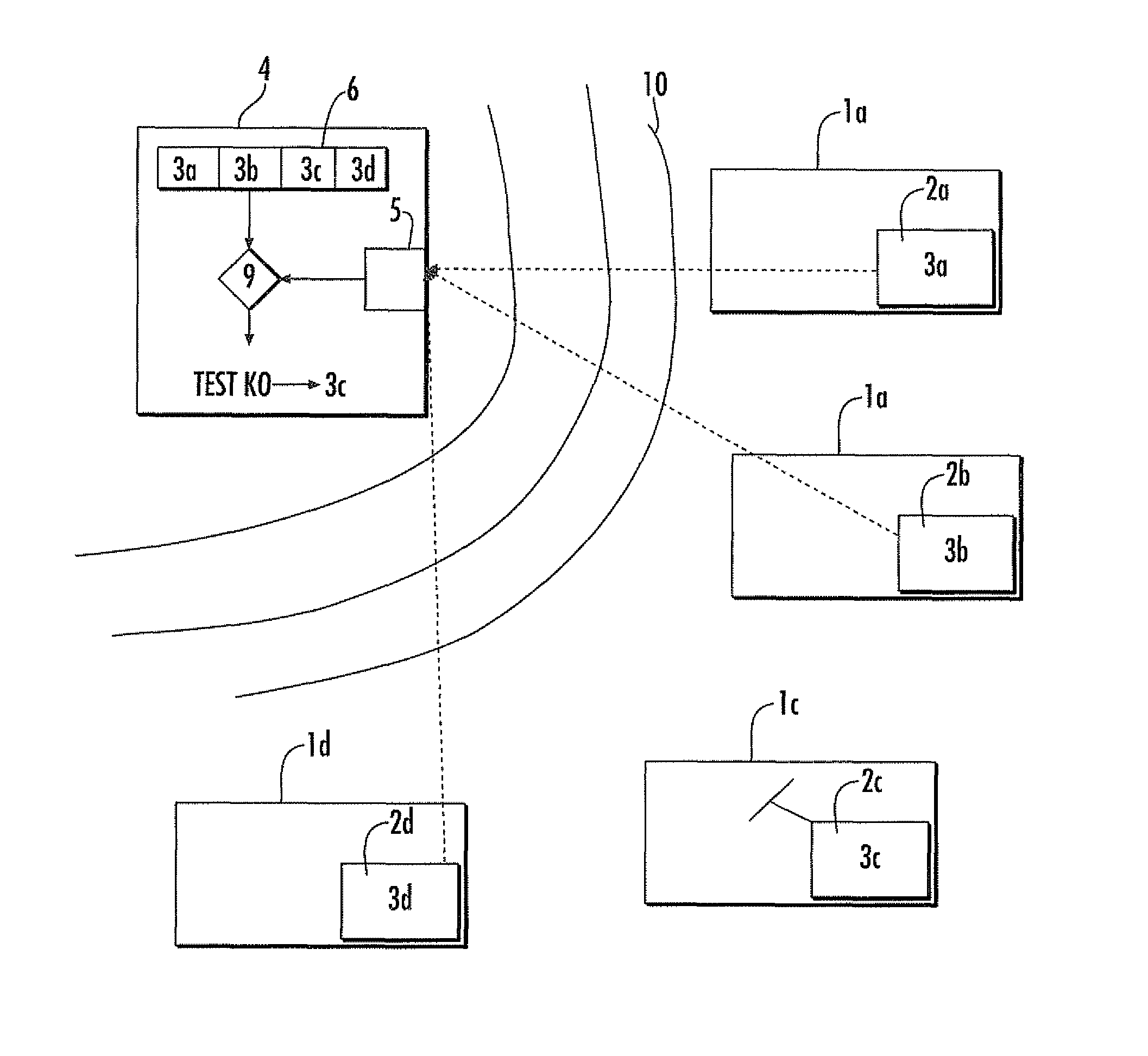
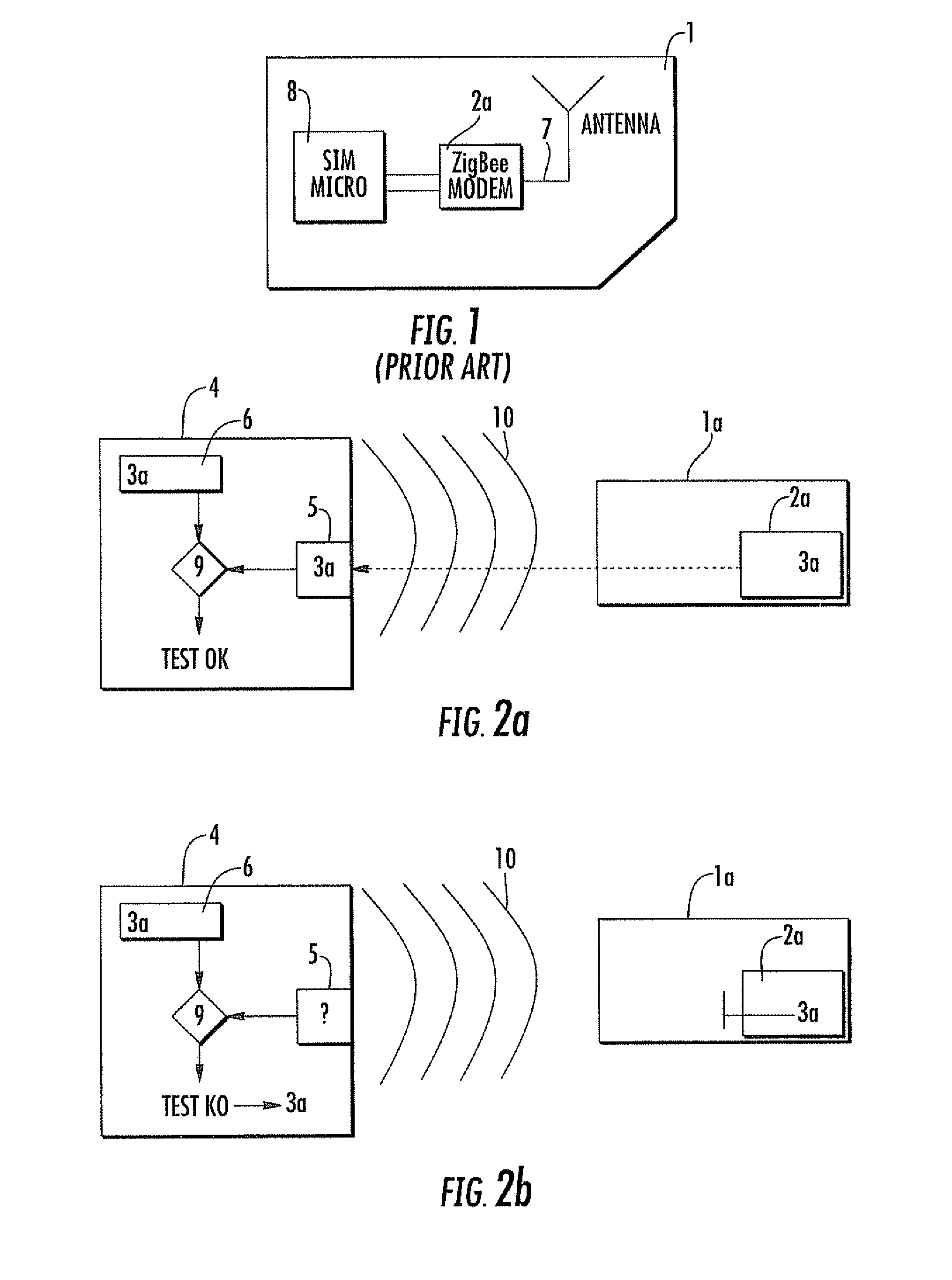
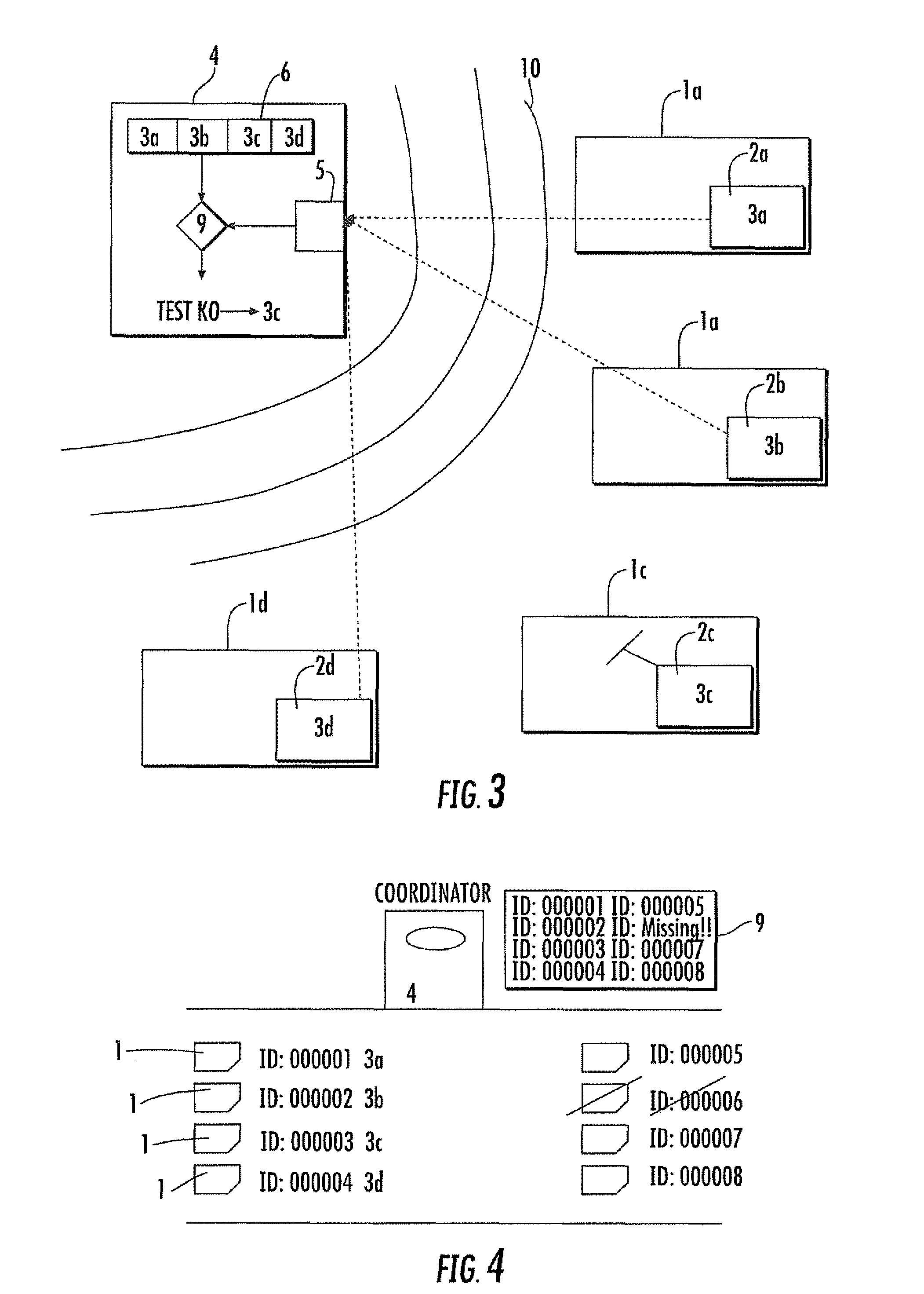
[0021]With reference to the annexed drawings, a test device 4 for testing an IC Card 1a includes a ZigBee device 2a. The test device 4 initializes a ZigBee network whereto the ZigBee device 2a may connect. More particularly, the ZigBee device 2a is associated to a predetermined Personal Area Network (PAN) Identifier 3a, stored in a memory portion of the IC Card 1a. The ZigBee device 2a connects to the ZigBee network and transmits the predetermined PAN Identifier 3a to the test device 4. However, if the ZigBee device 2a is defective, it typically cannot transmit the corresponding PAN Identifier 3a over the ZigBee network so that the test device 4 does not receive such PAN Identifier 3a.

[0022]The predetermined PAN Identifier 3a of the IC Card 1a to be tested is pre-stored in a memory portion 6 of the test device 4. More particularly, the wording “pre-stored” has been used for specifying that such PAN Identifier 3a is stored in the memory portion 6 before the test device 4 and the Zig...


PUM


Abstract

A method for testing a ZigBee device included in an IC Card includes associating a predetermined Personal Area Network (PAN) Identifier to the ZigBee device, and providing a test device, for initializing a ZigBee network. The method may include connecting the ZigBee device to the ZigBee network and transmitting the corresponding PAN Identifier to the test device. The method may include returning a fault message, indicative of a failure of connecting and transmitting, if the test device does not receive the PAN Identifier. The predetermined PAN Identifier may be stored in a memory portion of the test device and include, in the fault message, the PAN Identifier if the test device does not receive the PAN Identifier, in order to identify the ZigBee device as a defective device.

Description

FIELD OF THE INVENTION[0001]The present invention relates to a method for testing a ZigBee device included in an IC Card. The present invention also relates to a test device for testing a ZigBee device of the type included in an IC Card and associated to a predetermined Personal Area Network (PAN) Identifier.BACKGROUND OF THE INVENTION[0002]A method for testing an integrated circuit (IC) Card may include a phase for checking that hardware and software resources of the IC Card may communicate with a read-write device, according to a predetermined communication standard. More particularly, the IC Card may include a System on Chip including a memory portion, microcontroller, and a set of contact pads for an electrical connection with the read-write device.[0003]As schematically represented in FIG. 1, the IC Card 1 may also include a ZigBee device 2a including an antenna 7 for wireless communication with a ZigBee Controller, according to a standard IEEE 802.15.4. The method for testing ...

Claims


Application Information

Patent Timeline
Patent Type & Authority Patents(United States)
IPC IPC(8): G06F11/00
CPCH04W24/00H04W8/26H04W28/04H04W84/18
Inventor LONGO, RAFFAELE
Owner STMICROELECTRONICS INT NV
Learn More