
Method and Device for Photometrical Charting of a License Plate for a Vehicle

Pending Publication Date: 2021-11-25
TECHNOTEAM HLDG GMBH
View PDF1 Cites 0 Cited by
  • Summary
  • Abstract
  • Description
  • Claims
  • Application Information

AI Technical Summary

Benefits of technology

The patent describes a method for improving the accuracy of luminance density images by transforming their pixel coordinates through shifting, scaling, rotating, or perspective distortion. This transformation process maximizes the similarity between the registered images, resulting in a better overall image. Additionally, the method allows for the detection of errors in the planning of the positioning device, which can prevent damage to the device and other components. The technical effects of this patent are improved accuracy and efficiency in the registration and planning of luminance density images.

Problems solved by technology

However, it is also possible that such image areas are partially overlapping.

Method used


Image

  • Method and Device for Photometrical Charting of a License Plate for a Vehicle
  • Method and Device for Photometrical Charting of a License Plate for a Vehicle
  • Method and Device for Photometrical Charting of a License Plate for a Vehicle

Examples


Embodiment Construction

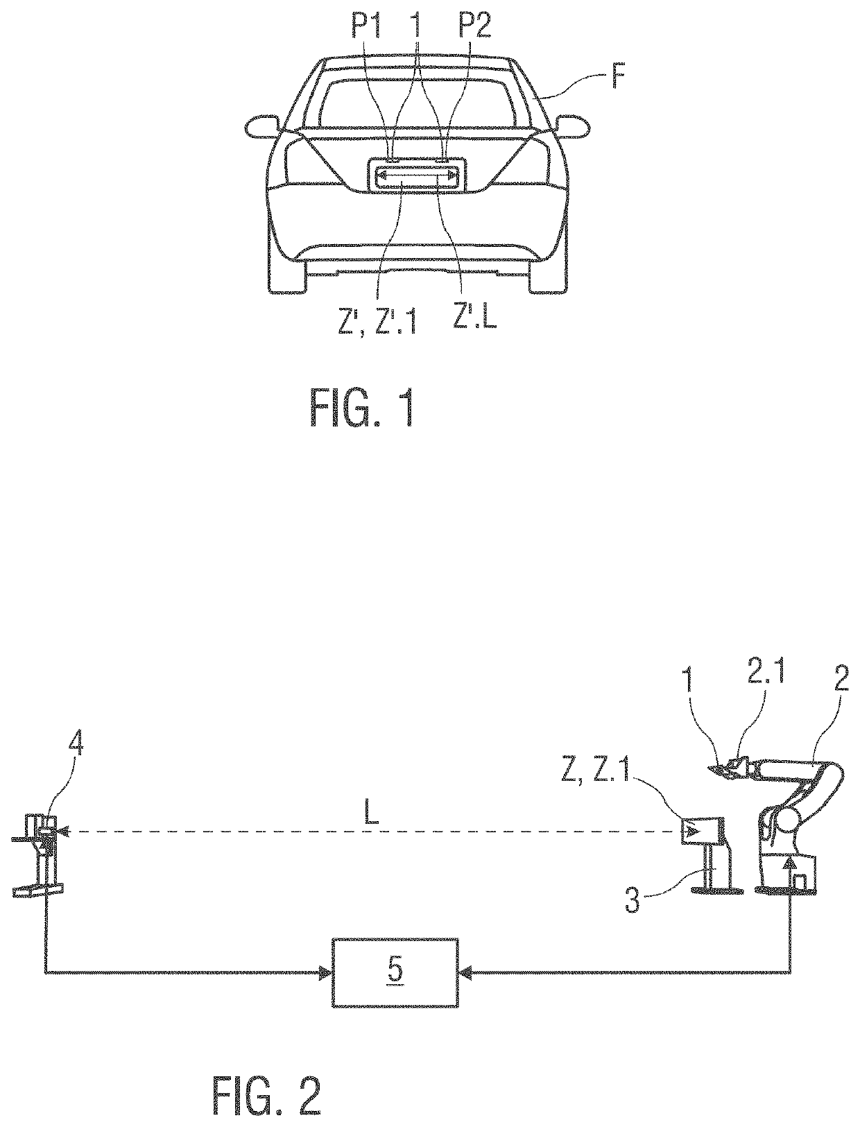
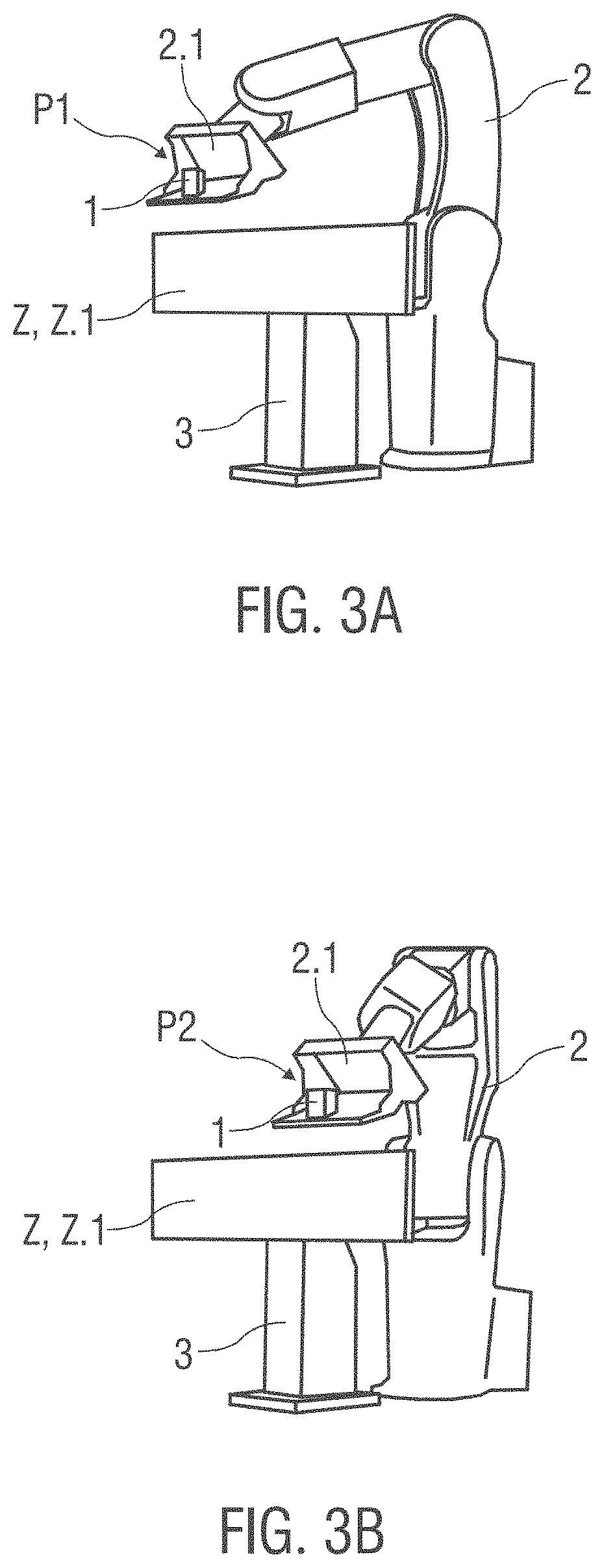
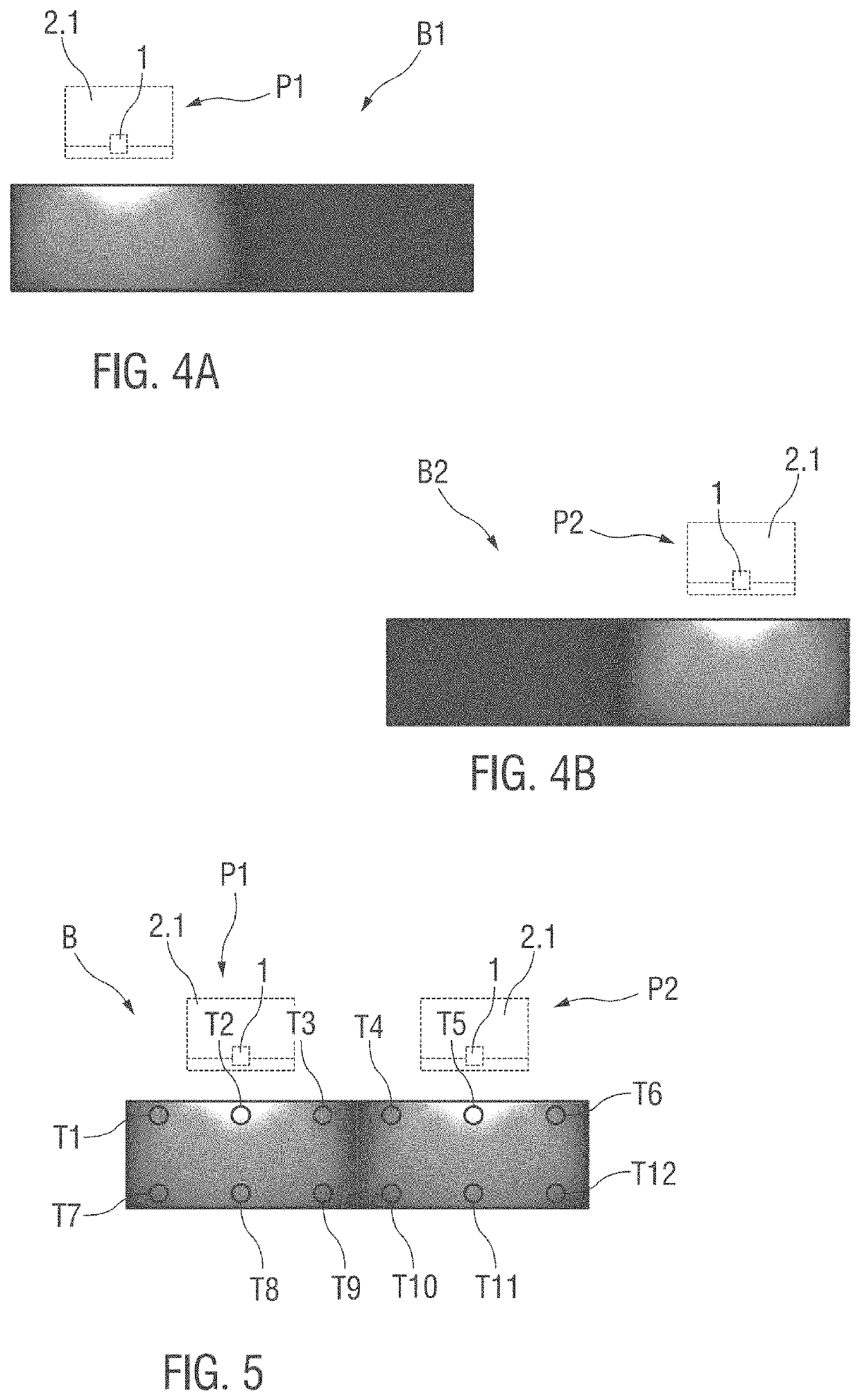
[0091]FIG. 1 shows a vehicle F with a license plate Z′ arranged thereon. The license plate Z′ has a reflecting surface Z′.1 and is illuminated by two license plate lights 1, which are arranged above the license plate Z′ along a longitudinal direction Z′.L distributed to a first position P1 and a second position P2. Herein, the positions P1, P2 describe the relative position of one respective license plate light 1 relative to the license plate Z′.

[0092]The license plate lights 1 must be configured and arranged such that the light from the license plate lights 1 reflected on the reflecting surface Z′.1 is sufficient for reading the license plate Z′ in the dark from a distance of approximately 10 to 20 meters. The luminance distribution reflected by the license plate Z′ illuminated by the license plate lights 1 is specified in standards. Measurement methods for determining if these standards are complied with are known in the art, wherein a photometer is moved at a predetermined distan...


PUM


Abstract

The invention relates to a method for photometrical charting of a reflectance standard (Z) illuminated by a license plate light (1). A camera (4) releasable by a control unit (5) is arranged and aligned relative to a holding device (3) configured for holding a reflectance standard (Z) in such a way, that a luminance density image (B1, B2) recorded by the camera (4) at least covers the reflective surface (Z.1) of a reflectance standard (Z) held by the holding device (3). A license plate light (1) is arranged in a positioning device (2) which is movable by the control unit (5). The positioning device (2) is controlled by the control unit (5) in such a way that the license plate light (1) arranged therein is traversed to at least one position (P1, P2), optionally to multiple positions (P1, P2) sequentially, relative to the reflectance standard (Z) arranged in the holding device (3) and held there. In each position (P1, P2), recording of at least one luminance density image (B1, B2) is triggered. An overall image (B) is formed from the recorded luminance density images (B1, B2) recorded by the camera (4). Furthermore, the invention relates to an arrangement for performing this method.

Description

CROSS-REFERENCE TO RELATED APPLICATION[0001]This application claims priority to German patent application no. 10 2020 206 275.7 filed on May 19, 2020, which is hereby incorporated by reference in its entirety.BACKGROUND1. Field of Invention[0002]The invention relates to a method and to an arrangement for photometrical charting of a license plate for a vehicle.2. Background Art[0003]The visibility of illuminated license plates of a vehicle is subject to legal and normative regulations, inter alia the norms ECER004, the Chinese Guobiao (GB) Standard GB 18408-2015 “Photometric characteristics of devices for the illumination of rear registration plates of motor vehicles and their trailers”, of the Society of Automotive Engineers (SAE) Standard SAE J578 “Color Specifications for Electrical Signal Lighting Devices” etc. Methods for checking compliance with these regulations comprise selective photometrical charting of an illuminated license plate.[0004]In a measurement setup for photometr...

Claims


Application Information

Patent Timeline
IPC IPC(8): G01N21/47G06T5/50G06T7/60G06T7/00G06K7/10
CPCG01N21/4785G06T5/50G01N2021/4704G06T7/97G06K7/10366G06T7/60G01J1/10G01J1/02G01J1/0242G01J1/0228G01J1/0266G01J1/0433G01J1/0488G01J2001/448G01J1/0238G01J1/0403G01M17/007G01M11/0214G01M11/0257G01M11/0292B60Q1/56
Inventor KRÜGER, UDOSCHWANENGEL, CHRISTIANTHIELE, TANJA
Owner TECHNOTEAM HLDG GMBH
Learn More