
Power transmission tower

a technology of power transmission tower and steel frame, which is applied in the direction of towers, buildings, constructions, etc., can solve the problems of difficult installation of conventional power transmission towers in places, and achieve the effects of enhancing the electric properties of the tower, reducing the size of the tower, and reducing the difficulty of installation

Active Publication Date: 2012-02-28
KOREA ELECTRIC POWER CORP
View PDF19 Cites 21 Cited by
  • Summary
  • Abstract
  • Description
  • Claims
  • Application Information

AI Technical Summary

Benefits of technology

The present invention provides a power transmission tower with an octagonal insulation arm arrangement that enhances mechanical strength and electrical properties. The tower includes a tower body, first through sixth main insulation arms, and first through eighth auxiliary insulation arms. The insulation arms are arranged radially and symmetrically about the tower body in a longitudinal direction. The angle between the main insulation arms is 45 degrees or multiple of 45 degrees. The tower can support the insulation arms for reinforcing mechanical strength to load. The use of octagonally arranged insulation arms allows for miniaturization and light weight of the power transmission tower, which makes it easier to establish in narrow areas. Additionally, the arrangement reinforces the mechanical strength and enhances the electric properties of the tower.

Problems solved by technology

Therefore, it is difficult to install the conventional power transmission tower in a place such as a downtown area where an area of a land under the power transmission is narrow.

Method used


Image

  • Power transmission tower
  • Power transmission tower
  • Power transmission tower

Examples


Embodiment Construction

[0024]The advantages, features and aspects of the invention will become apparent from the following description of the embodiments with reference to the accompanying drawings, which is set forth hereinafter.

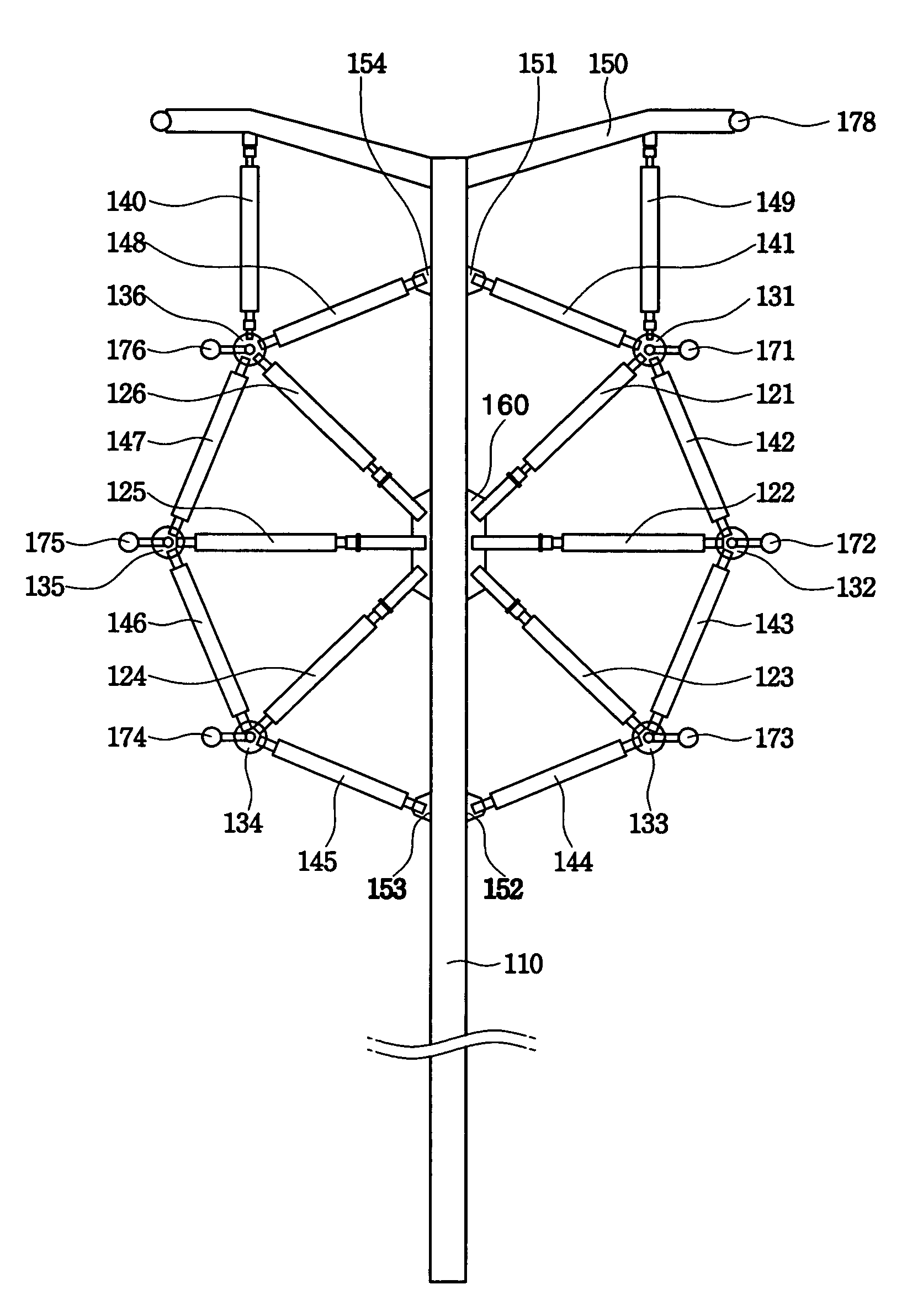
[0025]FIG. 3 shows a power transmission tower in accordance with an embodiment of the present invention. Referring to FIG. 3, a power transmission tower in accordance with an embodiment of the present invention includes a tower body 110, an arm 150 for an overhead earth wire, first through sixth main insulation arms 121˜126, first through sixth connection fittings 131˜136 and first through tenth auxiliary insulation arms 140˜149.

[0026]The tower body 110 has a steel pipe structure and is provided with a hub fitting 160 and first through fourth fixing fittings 151˜154. In the hub fitting 160, insertion holes into which the first through sixth main insulation arms 121˜126 are fixedly inserted, respectively may be formed. The first through fourth fittings 151˜154 are connected to one...


PUM


Abstract

Disclosed is a power transmission tower, which includes a tower body; first through sixth main insulation arms connected by one end thereof to the tower body with an angle with the tower body, respectively, and arranged radially and symmetrically about the tower body in a longitudinal direction; and first through eighth auxiliary insulation arms for selectively connecting the other end of the first through sixth main insulation arms and the tower body so that each of the auxiliary insulation arms constitutes each side of an octagon.Since the insulation arms are octagonally arranged, it is possible to reinforce a mechanical strength and enhance electric properties of the tower.

Description

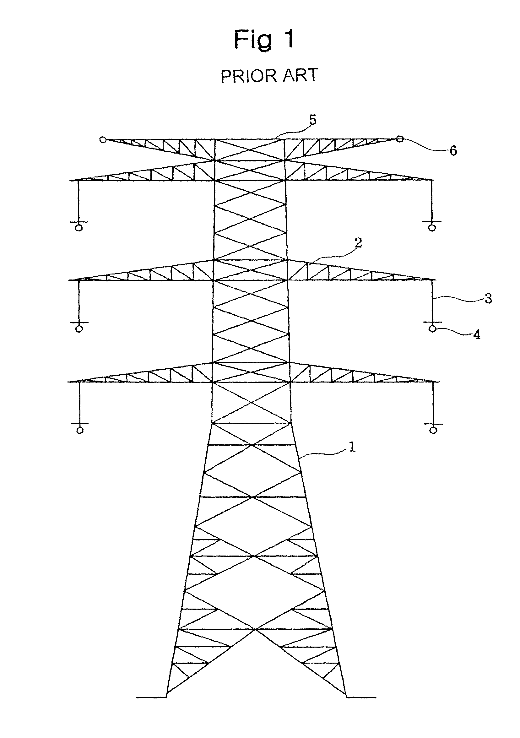
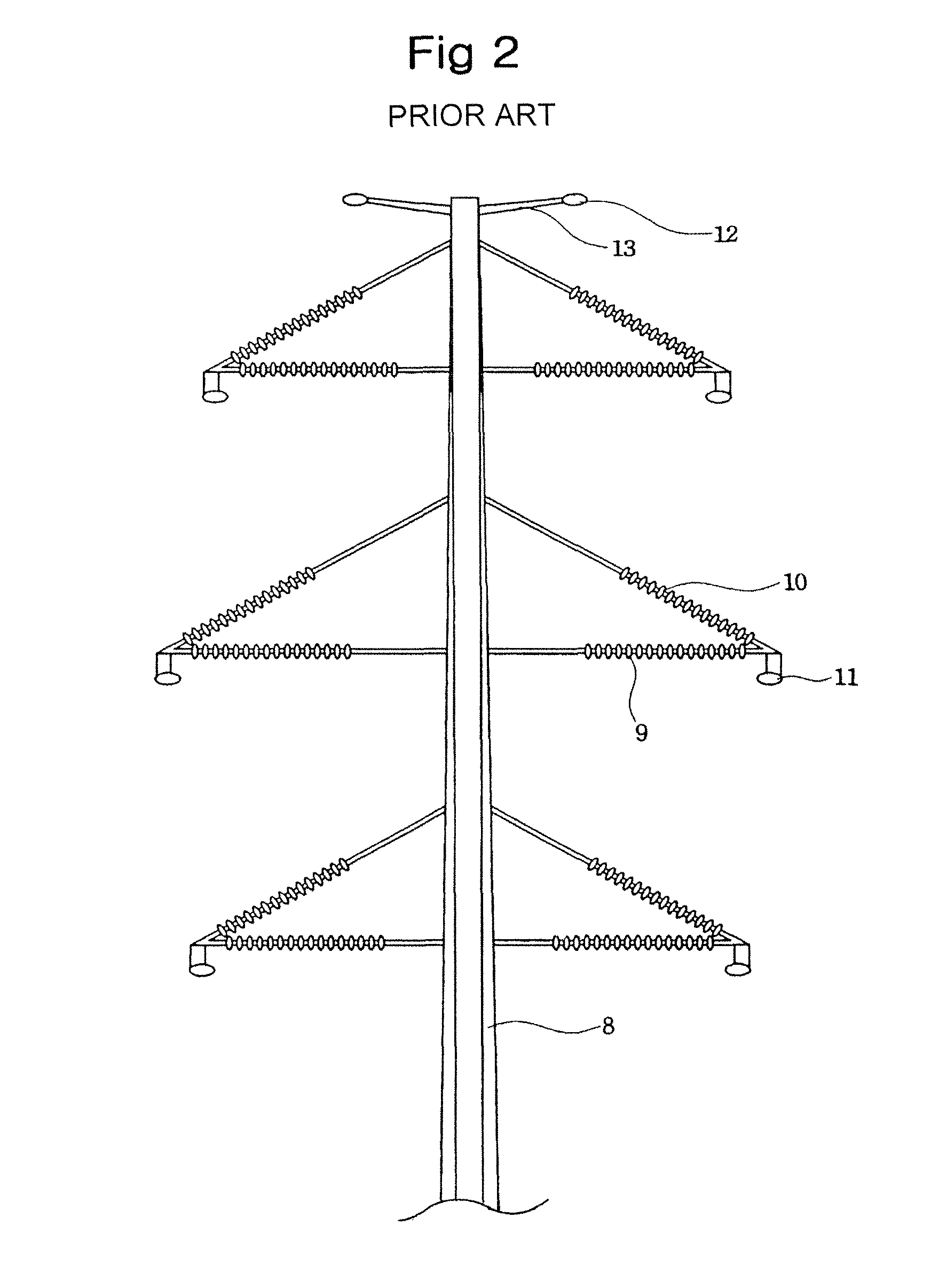
[0001]The present invention claims priority of Korean Patent Application No. 10-2008-0091313, filed on Sep. 17, 2008, which is incorporated herein by reference.BACKGROUND OF THE INVENTION[0002]1. Field of the Invention[0003]The present invention relates to a steel tower, and more particularly, to a power transmission tower.[0004]2. Description of Related Art[0005]A power transmission tower refers generally to a tower made of steel frame or steel reinforced frame for supporting power transmission lines. In the power transmission tower, a tower body of metal material is in contact with the earth. In order to insulate the power transmission line from the earth, an arm is used to maintain a clearance between the power transmission line and the tower body. Since the arm is made of a metal material, an insulator of porcelain material is used to insulate the arm from the power transmission line.[0006]FIG. 1 shows a conventional tower for two coupled three-phase power transmission. Referrin...

Claims


Application Information

Patent Timeline
Patent Type & Authority Patents(United States)
IPC IPC(8): E04H12/08E04H12/24H02G7/00
CPCE04H12/24H02G7/20E04H12/08H02G7/02
Inventor LEE, WON-KYOLEE, DONG-IISHIN, KOO-YONGCHOI, IN-HYUK
Owner KOREA ELECTRIC POWER CORP
Learn More