
Electric unit having capacitor

a technology of capacitors and electric units, applied in the direction of capacitor details, electrical equipment construction details, transportation and packaging, etc., can solve the problems of deterioration of capacitor performance and miniaturization of electric equipment, and achieve the effect of suppressing an increase in capacitor temperatur

Active Publication Date: 2012-01-24
DENSO CORP
View PDF22 Cites 2 Cited by
  • Summary
  • Abstract
  • Description
  • Claims
  • Application Information

AI Technical Summary

Benefits of technology

Effectively suppresses the increase in capacitor temperature, reducing the risk of performance deterioration and enhancing the reliability of the electric unit by reflecting heat radiation and facilitating efficient heat dissipation.

Problems solved by technology

Space for the member only for closing the opening of the case can thus be reduced, which leads to miniaturization of the electric equipment.
When the emitted heat ray is absorbed into the capacitor to increase a temperature of the capacitor, performance of the capacitor may deteriorate.

Method used


Image

  • Electric unit having capacitor
  • Electric unit having capacitor
  • Electric unit having capacitor

Examples


case 510

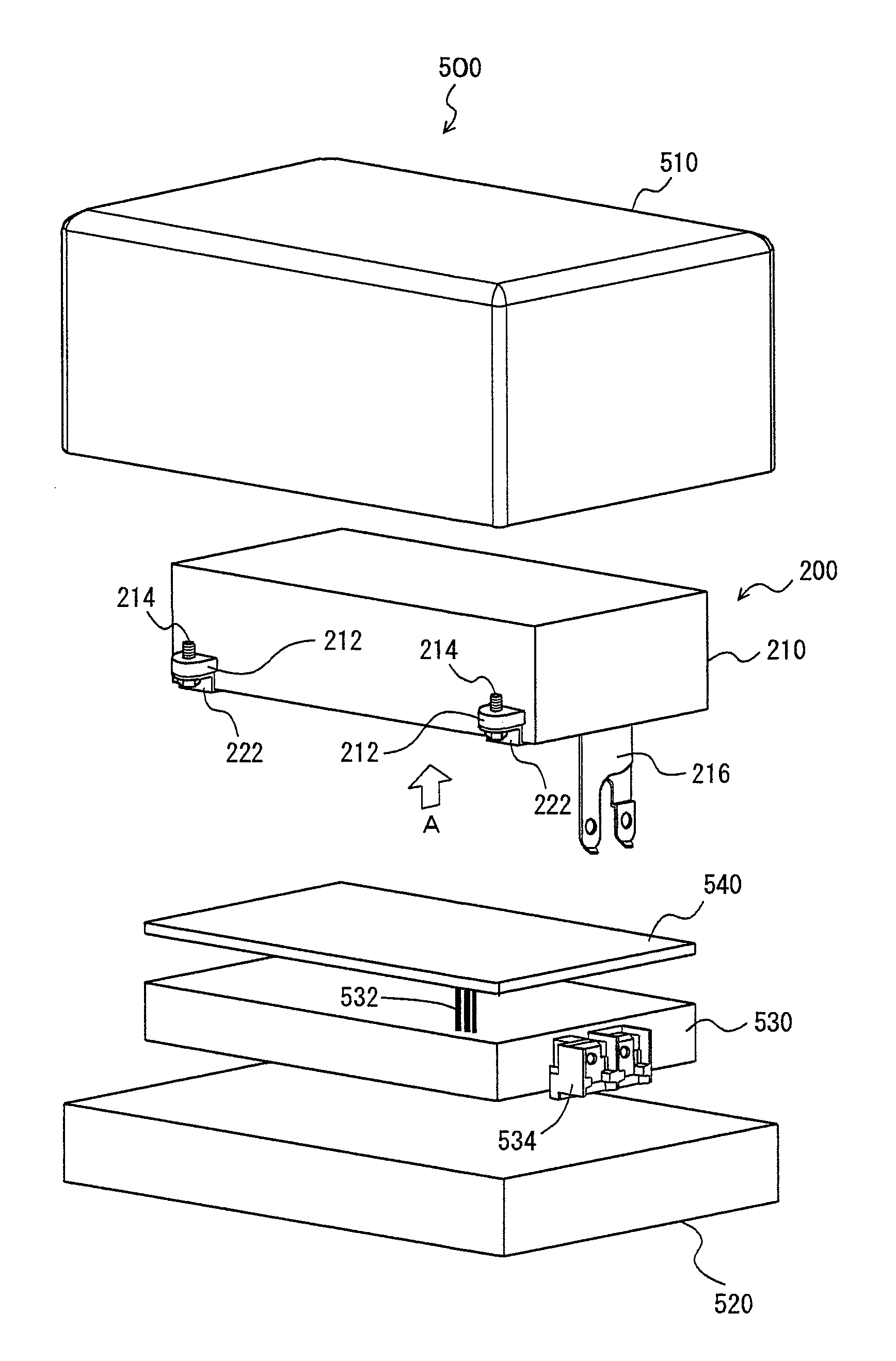
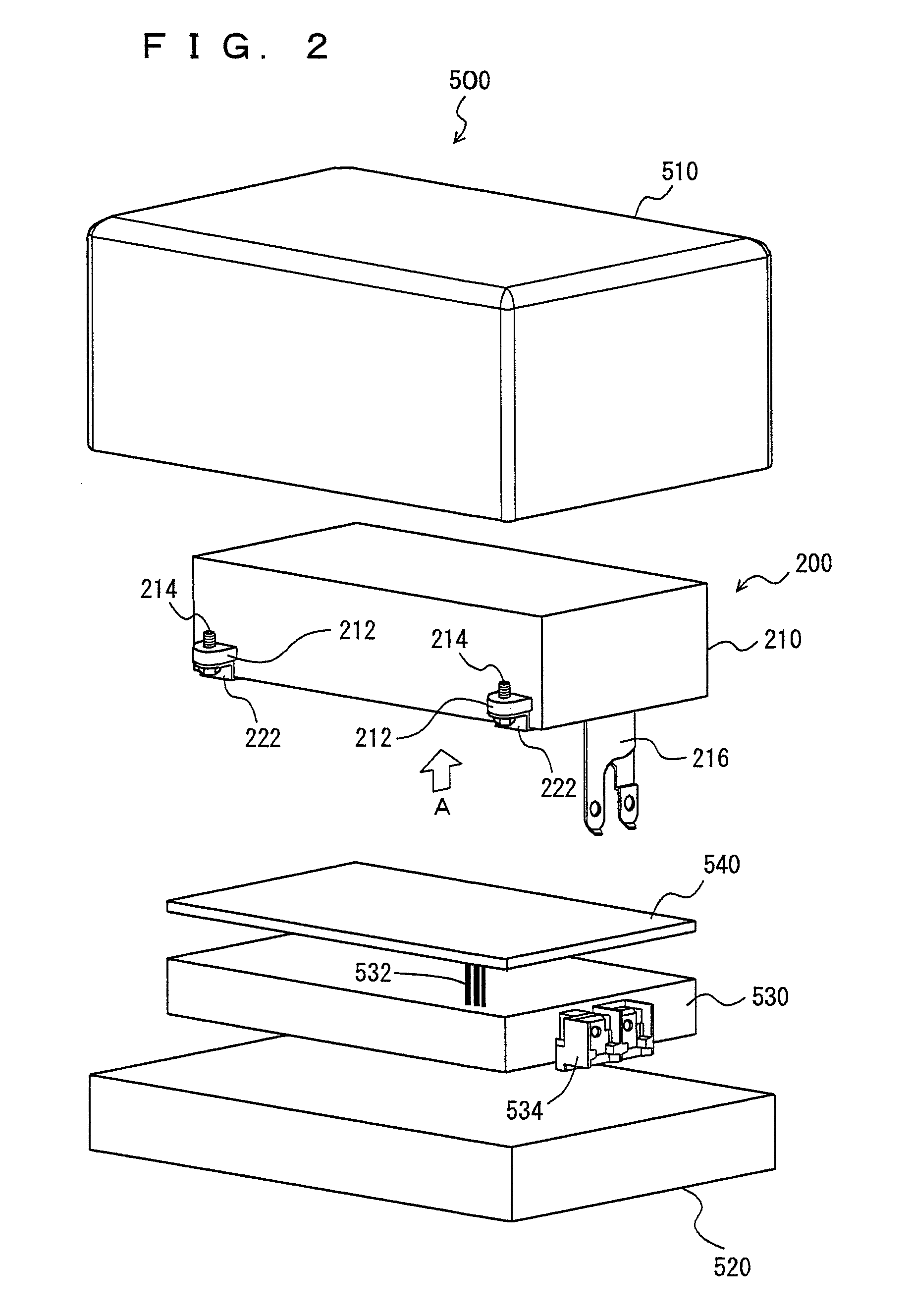
[0039]Case 510 is a casing in a substantially parallelepiped form with an open lower portion. A lower peripheral surface of case 510 and bottom plate 520 are fixed with bolts (not shown) to abut each other.

[0040]Interior space of PCU 500 formed by case 510 and bottom plate 520 accommodates IPM 530, a control substrate 540, and capacitor 200.

[0041]IPM 530 is provided to abut an upper surface of bottom plate 520. It is noted that IPM 530 may be provided to abut the upper surface of bottom plate 520 with a heat radiation plate (not shown) interposed therebetween.

[0042]Control substrate 540 is a rectangular plate having mounted thereon a control circuit including electronic components such as a gate driver, a transformer and the like, and is provided above IPM 530. Control substrate 540 is electrically connected to IPM 530 via connection lines 532. In response to an instruction signal from the ECU, the control circuit mounted on control substrate 540 generates a control signal for contr...


PUM


Abstract

A PCU has an inside sealed by a case made of aluminum and a bottom plate. Interior space of the PCU accommodates an IPM, a control substrate, and a capacitor. The IPM is provided to abut an upper surface of the bottom plate. The control substrate is a rectangular plate having mounted thereon a control circuit including electronic components such as a gate driver, a transformer and the like, and is provided above the IPM. The capacitor is accommodated in a housing in a substantially parallelepiped form. A reflector made of aluminum of high thermal reflectivity and high thermal conductivity is provided on the entire lower surface of the capacitor.

Description

TECHNICAL FIELD[0001]The present invention relates to an electric unit having a capacitor, and more particularly to an electric unit accommodating a capacitor and an electronic component different from the capacitor within a casing.BACKGROUND ART[0002]Electric cars and hybrid vehicles having a motor as a driving source have been put to practical use. Electric power from a battery is boosted and converted to be supplied to the motor. Electronic components (e.g. a semiconductor element constituting an inverter) for supplying the electric power to the motor are usually accommodated in a casing and protected from the outside. In recent years, from the viewpoint of securing of space, there has been a demand for miniaturization of the casing for accommodating the electronic components for supplying the electric power to the motor. Such a technique of miniaturizing the casing is disclosed in Japanese Patent Laying-Open No. 2004-312925, for example.[0003]Electric equipment disclosed in Japa...

Claims


Application Information

Patent Timeline
Patent Type & Authority Patents(United States)
IPC IPC(8): H05K7/20
CPCH01G2/106H01G2/14H01G9/08Y02T10/7022Y02T10/70
Inventor HAMATANI, TAKASHI
Owner DENSO CORP
Learn More