
Grinding machine and method for grinding work pieces between centers and for centerless grinding in which the work piece can be supported between a grinding wheel, and a regulating wheel either between centers on a work piece axis or on a rest for centerless grinding

a technology of centerless grinding and grinding machine, which is applied in the direction of grinding machine components, grinding/polishing apparatus, grinding machines, etc., can solve the problems of high tool cost, high cost of centering, and the need for work piece drivers, so as to achieve greater flexibility and reliability

Active Publication Date: 2012-01-24
TSCHUDIN URS
View PDF14 Cites 3 Cited by
  • Summary
  • Abstract
  • Description
  • Claims
  • Application Information

AI Technical Summary

Benefits of technology

[0009]The invention is based on the objective of disclosing an improved grinding machine that combines the advantages of “grinding between centers” with those of “centerless grinding”. The invention also aims to disclose a method that makes it possible to achieve greater flexibility and reliability in the manufacture of ground products.
[0011]Due to the fact that the drive of the work piece is realized via the regulating wheel in both grinding modes, the work piece driver that would otherwise be required while grinding between centers can be eliminated. The rotational monitoring of the work piece is simplified and can also be automated since a means is provided for measuring the contact pressure between the regulating wheel and the work piece.
[0018]It is advantageous that the work piece support may also feature an arrangement of centers for simultaneously processing a number of work pieces with center pairs that are arranged behind one another or above one another or behind one another and above one another. This makes it possible to simultaneously process several work pieces. It goes without saying that the grinding machine also needs to be equipped with a corresponding number of grinding wheels and regulating wheels in this case, but the construction-related additional costs for the grinding machine can be maintained relatively low because no additional drives are required for the grinding wheel and the regulating wheel, as well as for adjusting the grinding wheel, the regulating wheel and the work piece support.
[0022]All in all, the basically simple design of the grinding machine in accordance with the invention makes it possible to achieve a versatility that could not be realized so far with conventional designs.

Problems solved by technology

The disadvantage of this method is the higher costs caused by the need for centers.
However, its disadvantages are the usually quite high tool costs and the fact that shafts are, under certain circumstances, no longer concentric to centers or bores, etc.
In this case, it is disadvantageous that a work piece driver is still required and that the change-over between operating modes is relatively complicated.
In this case, however, the regulating wheel of the grinding machine rotates with a relatively slow speed in comparison with the grinding wheel.
Although the grinding machine according to U.S. Pat. No. 3,903,655 utilizes certain elements that are also used in centerless grinding (e.g. driving the work piece via a regulating wheel), this machine is not designed for a flexibility that makes it possible to carry out “grinding between centers” as well as “centerless grinding”, and the carriages for the grinding wheel, the regulating wheel and the work piece are all designed for realizing a precise and defined mechanical positioning.

Method used


Image

  • Grinding machine and method for grinding work pieces between centers and for centerless grinding in which the work piece can be supported between a grinding wheel, and a regulating wheel either between centers on a work piece axis or on a rest for centerless grinding
  • Grinding machine and method for grinding work pieces between centers and for centerless grinding in which the work piece can be supported between a grinding wheel, and a regulating wheel either between centers on a work piece axis or on a rest for centerless grinding
  • Grinding machine and method for grinding work pieces between centers and for centerless grinding in which the work piece can be supported between a grinding wheel, and a regulating wheel either between centers on a work piece axis or on a rest for centerless grinding

Examples


Embodiment Construction

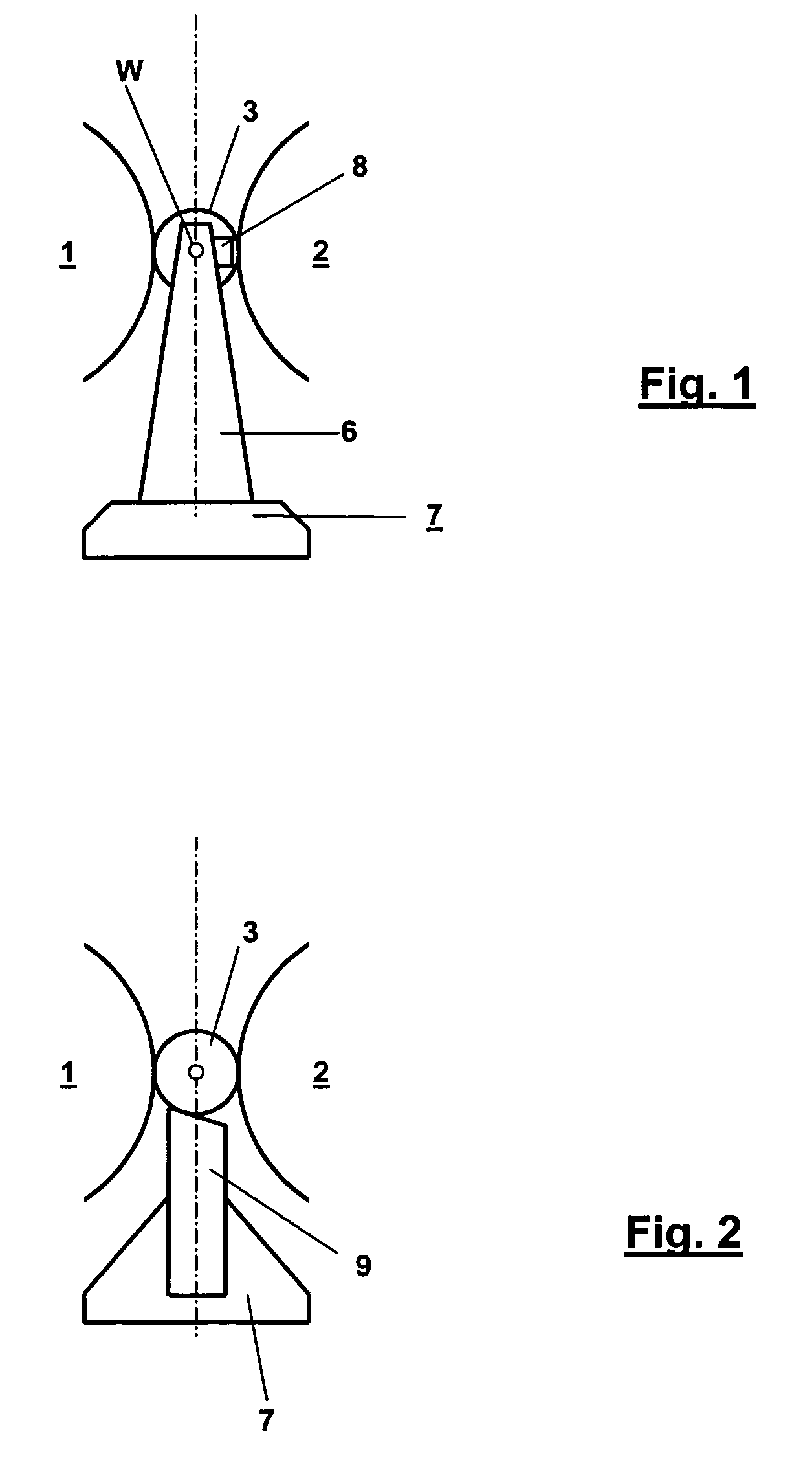
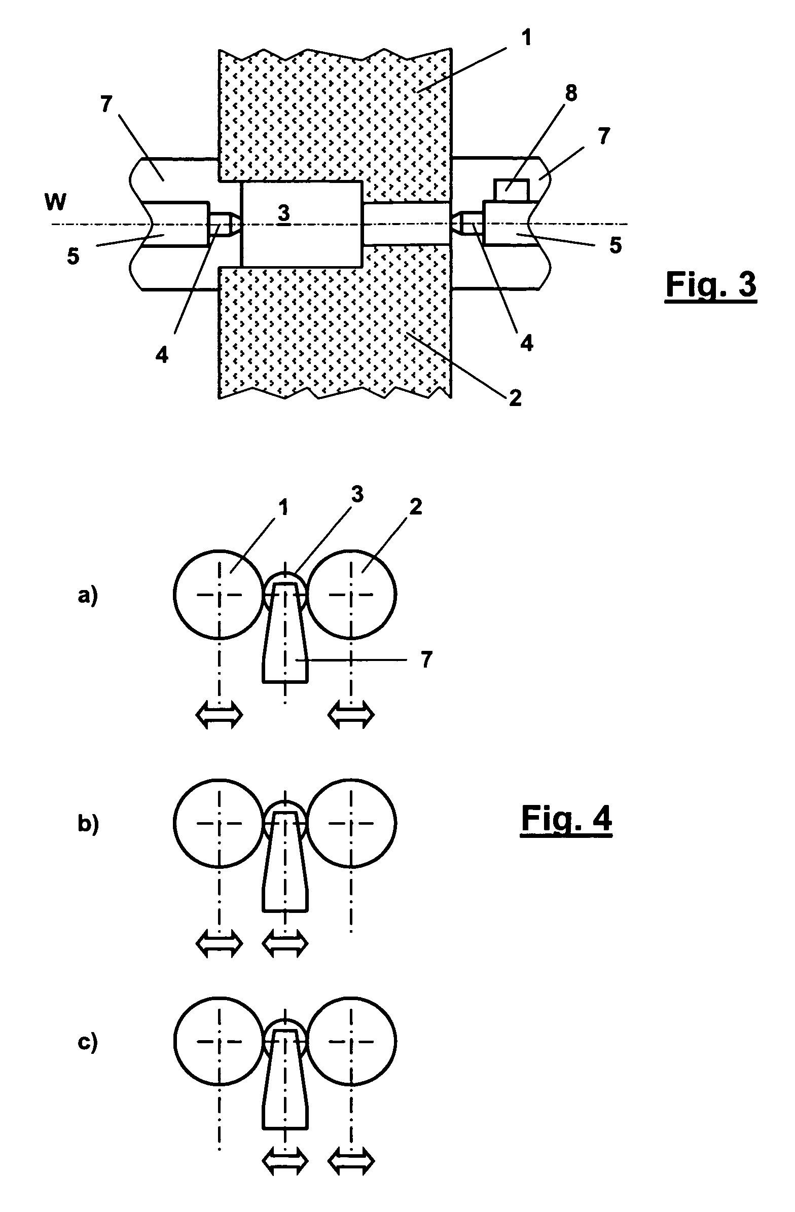
[0030]FIG. 1 shows a schematic representation of a device for the cylindrical grinding between centers which features a grinding wheel 1 and a regulating wheel 2. In this case, a work piece 3 to be processed is accommodated between centers 4 (in this respect, see also FIG. 3). The centers 4 define a work piece axis W together with the work piece 3. The centers 4 are situated on a footstock 5 that is arranged on a holder 6 of a work piece support 7. During the operation, i.e. while carrying out a grinding process, the work piece 3 is driven by the rotating regulating wheel 2. The grinding process is carried out with the rotating grinding wheel 1. As mentioned above, the advantages of grinding between centers can be seen, in particular, in the centricity of all diameters ground on the work piece 3 referred to the work piece axis W.

[0031]In addition, a pressure sensor 8 is provided as a means for measuring the contact pressure of the regulating wheel 2 on the work piece 3. In this case...


PUM

PropertyMeasurementUnit
contact pressureaaaaaaaaaa
diametersaaaaaaaaaa
sizesaaaaaaaaaa

Abstract

A grinding machine for grinding work pieces between centers, as well as for centerless grinding, features a drive for a grinding wheel and a drive for a regulating wheel. The work piece can be supported between the grinding wheel and the regulating wheel either between centers on a work piece axis or on a rest for centerless grinding. The driving axis of the regulating wheel and the work piece axis are parallel, and the wheels can be adjusted relative to the work piece independently of one another. The drive of the regulating wheel serves for driving the work piece while grinding between centers or for driving the work piece during centerless grinding. In addition, a means for measuring the contact pressure of the regulating wheel on the work piece is provided for grinding between centers. This means may consist, for example, of a pressure sensor.

Description

CROSS-REFERENCES TO RELATED APPLICATIONS[0001]This application claims the priority of Swiss Patent Application No. 0194 / 07, filed Feb. 6, 2007, the disclosure of which is incorporated herein by reference.BACKGROUND OF THE INVENTION[0002]The invention pertains to a grinding machine for grinding work pieces between centers and for centerless grinding, as well as to a grinding method for grinding a work piece between centers.[0003]The invention pertains, in particular, to a grinding machine that makes it possible to combine the advantages of grinding between centers with those of centerless grinding.[0004]In the well-known traditional method of grinding between centers, the main advantage can be seen in that all ground diameters have the same well-defined center on the work piece axis that lies between the centers. The disadvantage of this method is the higher costs caused by the need for centers. The work piece frequently needs to be processed in steps because a driving device initial...

Claims


Application Information

Patent Timeline
Patent Type & Authority Patents(United States)
IPC IPC(8): B24B1/00B24B49/00B24B51/00
CPCB24B5/02B24B5/18B24B49/16
Inventor TSCHUDIN, URS
Owner TSCHUDIN URS
Learn More