
Tubular joint

a tubular joint and joint technology, applied in the direction of hose connection, coupling, cable termination, etc., can solve the problems of requiring a significant fitting force for locking elements, unable to allow significant angular offset, and the seal risk of being extruded or even expelled from between the bell end and the spigot end

Active Publication Date: 2012-01-17
SAINT GOBAIN PAM SA
View PDF22 Cites 34 Cited by
  • Summary
  • Abstract
  • Description
  • Claims
  • Application Information

AI Technical Summary

Benefits of technology

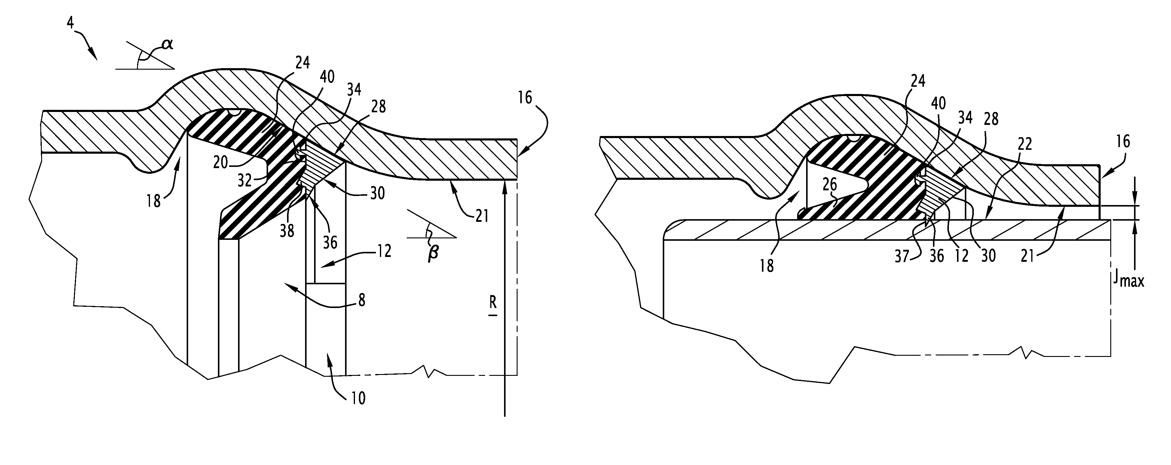
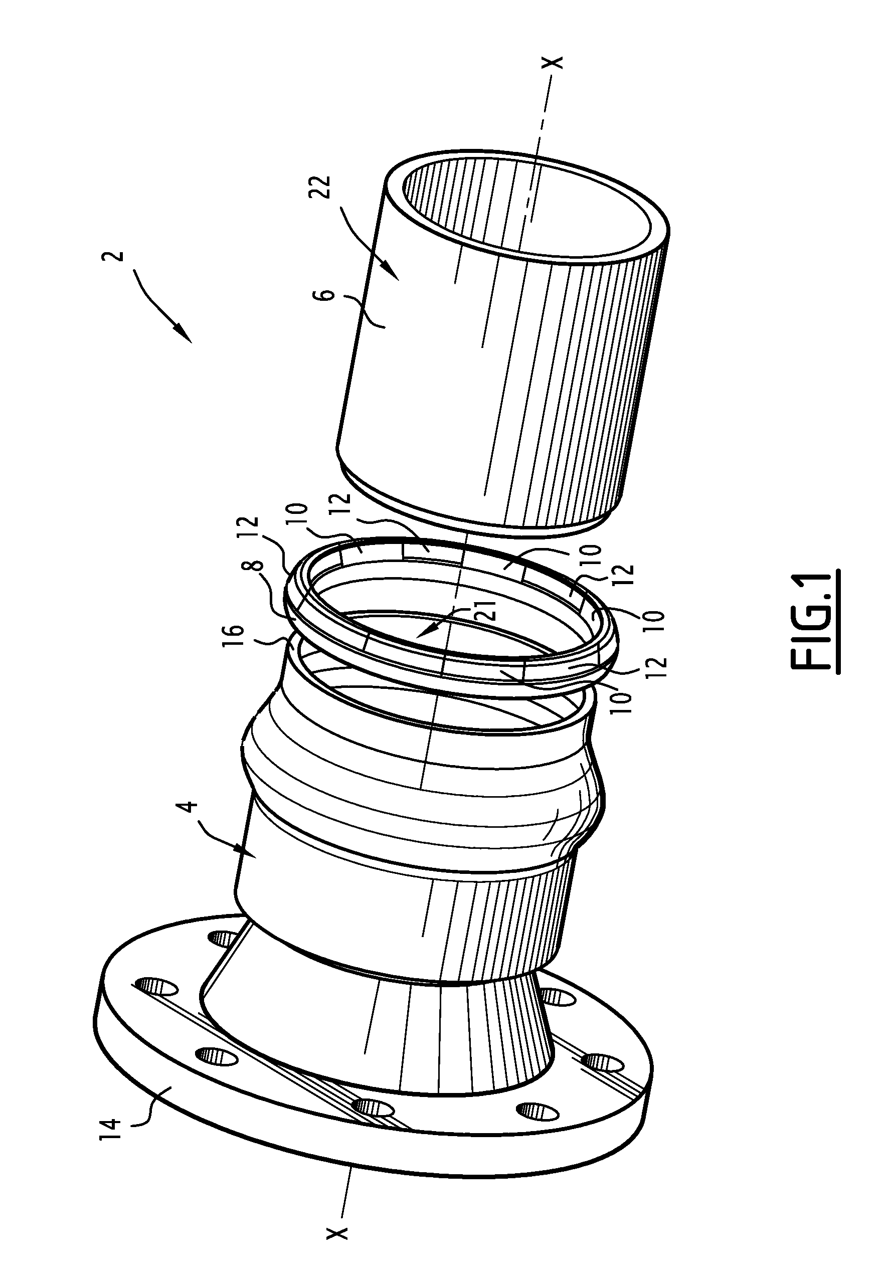
[0007]The object of the invention is to overcome these drawbacks and to propose a tubular joint which reduces the forces involved in fitting the spigot end in the bell end and allows effective locking in a wide range of clearances.

Problems solved by technology

In addition, the seal risks being extruded or even expelled from between the bell end and the spigot end.
If there is a slight clearance between the bell end and the spigot end, however, these locking elements require a significant fitting force since the axial displacement of the locking elements during insertion of the spigot end necessitates the compression of a large volume of elastomer.
In addition, these tubular joints do not allow a significant angular offset between the spigot end and the bell end.
These locking elements require significant fitting forces if there is a slight clearance between the bell end and the spigot end.
In addition, if the clearance between the pipe elements is great and if the internal pressure is high, there is the risk that the locking element will not resist the recoil of the spigot end and will turn back completely, making the lock inoperative.

Method used


Image

  • Tubular joint
  • Tubular joint
  • Tubular joint

Examples


second embodiment

[0076]FIG. 7 shows the tubular joint according to the invention which differs from the joint as follows.

[0077]Advantageously, the radially internal face 30 of the locking insert 12 is equipped with an auxiliary fixing tooth 50. this auxiliary tooth 50 is disposed remotely from the main fixing tooth 36, that is to say on the side of the free extremity 16 of the bell end 4. This auxiliary fixing tooth 50 is adapted to guarantee locking when the clearance J is small, that is to say close to the minimum clearance Jmin, while thus opposing the sliding of the main fixing tooth 36 on the external surface 22 of the spigot end 6, this risk of sliding potentially being high with slight clearance owing to the small angle of inclination to the external surface 22 of the bearing reaction in the region of this fixing tooth 36. The auxiliary fixing tooth 50 comprises an auxiliary fixing surface 52 which forms an auxiliary angle δ with the internal face 30 of the locking element. This auxiliary ang...

third embodiment

[0078] described with reference to FIGS. 8 and 9, the anti-extrusion elements 10 are inserted between the locking elements 12 which are uniformly distributed round the periphery of the seal 8. The anti-extrusion elements 10 are separated from the locking elements 12 by a circumferential spacer 56 which is integral with the seal 8, this spacer 56 having a small circumferential dimension so as not to be extruded under the influence of the internal pressure. These spacers improve the resilience of the seal 8 and thus facilitate the deformation thereof for the introduction thereof into the bell end.

[0079]With regard to fastening, the locking elements 12 and the anti-extrusion elements 10 are equipped with anchor studs 40 which are integral with the connection face 32, these studs 40 being over-moulded in the elastomer of the seal 8. Advantageously, the anchor studs 40 are covered with an adhesive beforehand to allow the studs 40 to adhere to the elastomer after injection thereof into th...

seventh embodiment

[0084]FIGS. 15 and 16 show a FIG. 15 is a perspective view of the seal 8 carrying the anti-extrusion elements 10 and the locking elements 12. FIG. 16 shows a portion of the seal 8, the elements 10 and 12 not being assembled. The seal 8 is equipped with locking elements 12 having the general shape of a planar arc of a ring. The locking elements 12 are formed from treated metal, for example from hardened steel, and are intended to lock the joint. An anti-extrusion element 10 of triangular section, which is intended to counteract the extrusion of the elastomer is fastened on the locking element 12. The anti-extrusion element 10 is made of rigid plastics material or of untreated metal, for example of mild steel. The two elements 10 and 12 are connected to one another by screws 40 of which the head 40A is over-moulded in the elastomer of the seal 8.


PUM


Abstract

This tubular joint includes a bell end (4) which is equipped with an internal groove (18) and in which is inserted a spigot end (6), a seal (8) and a locking element (12). The groove forms a groove wall (20). The spigot end (6) and the bell end (4) define a radial clearance (J). The locking element (12) includes a fixing tooth (36) and a contact face (28) for application against the wall (20) when the clearance (J) is within a first range of clearances. When the clearance is within a second range of clearances, the locking element (12) forms a rocking point (34) for rocking round the groove wall (20) and the fixing tooth (36) bites into the external surface (22) by a flying buttress effect of the locking element (12).

Description

FIELD OF THE INVENTION[0001]The present invention relates to a tubular joint of the type comprising a bell end of a first pipe element, the bell end extending along a central axis, being equipped with an internal groove and a free extremity in which is inserted a spigot end of a second pipe element, the internal groove forming a truncated cone-shaped groove wall which forms a first angle with the central axis and is inclined to the central axis while narrowing toward the free extremity of the bell end, a seal disposed in the internal groove, at least one locking element adapted to lock the spigot end relative to the bell end, the spigot end and the bell end defining a radial clearance between themselves, this clearance being able to be situated either in a first range of clearances or in a second range of clearances, the clearances of the second range of clearances being smaller than the clearances of the first range of clearances.[0002]It applies, in particular, to pipes conveying ...

Claims


Application Information

Patent Timeline
Patent Type & Authority Patents(United States)
IPC IPC(8): F16L17/00
CPCF16L17/035F16L21/08F16L37/0845
Inventor VITEL, JEAN-PIERRERENARD, PHILIPPEGROJEAN, DANIEL
Owner SAINT GOBAIN PAM SA
Learn More