Negative pressure control apparatus for vehicle braking operation
a control apparatus and negative pressure technology, applied in the direction of braking systems, combustion air/fuel air treatment, instruments, etc., can solve the problems of not being able to obtain the negative pressure required and it is not easy to obtain the negative pressure for a braking operation
- Summary
- Abstract
- Description
- Claims
- Application Information
AI Technical Summary
Benefits of technology
Problems solved by technology
Method used
Image
Examples
first embodiment
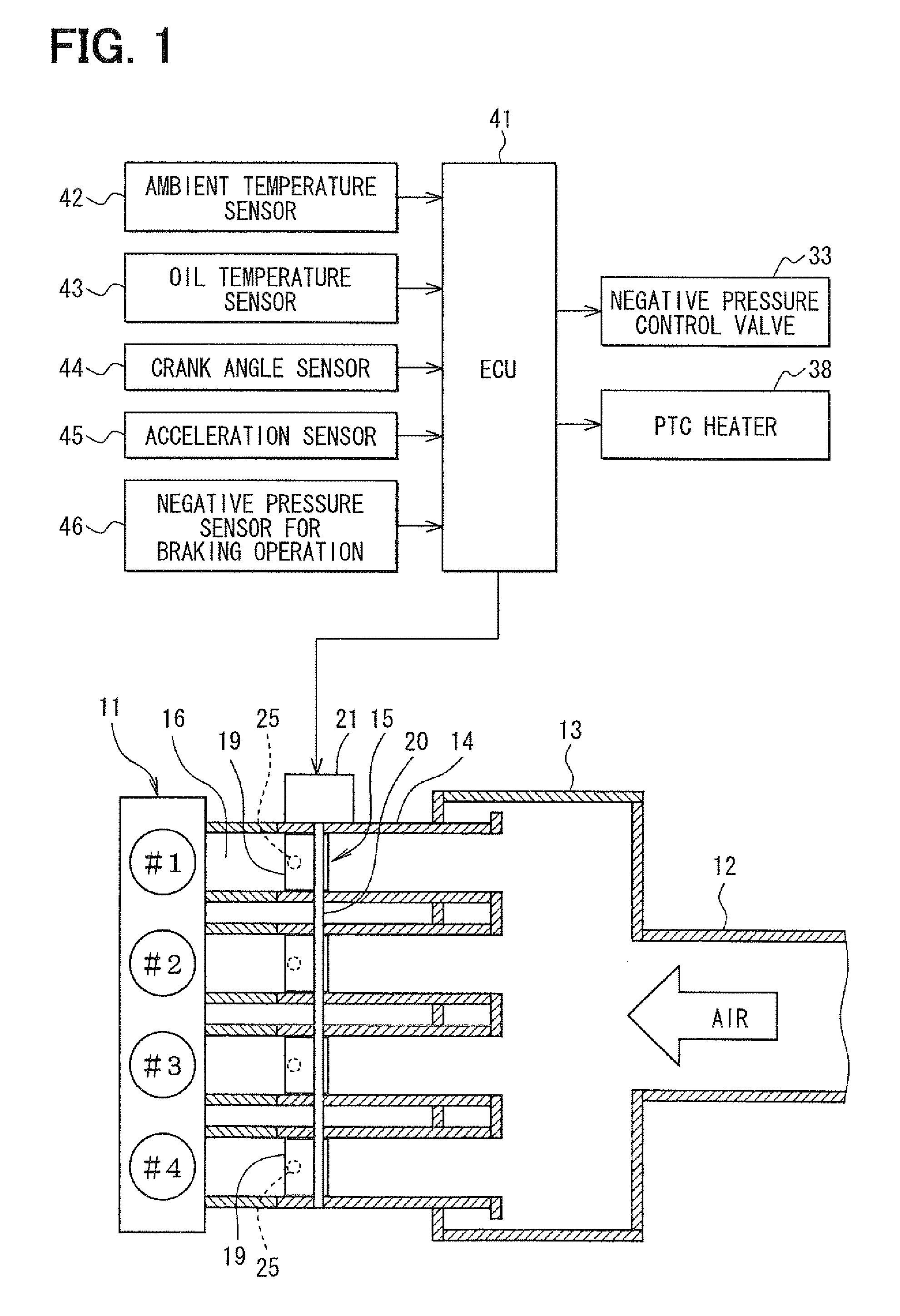
[0046]A first embodiment of the present invention will be explained with reference to FIGS. 1 to 14.
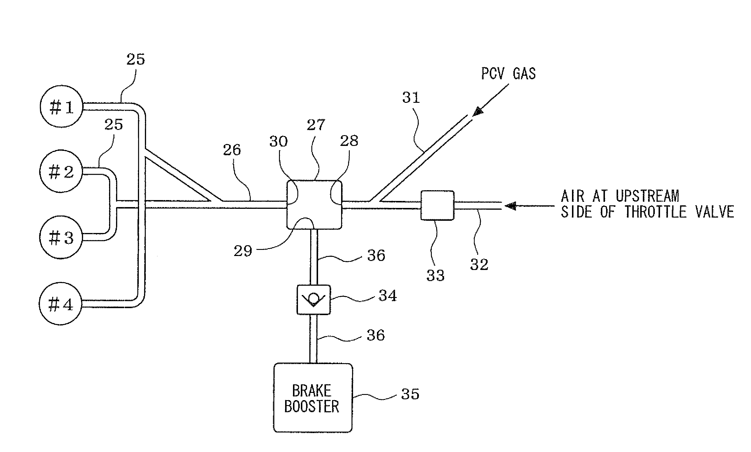
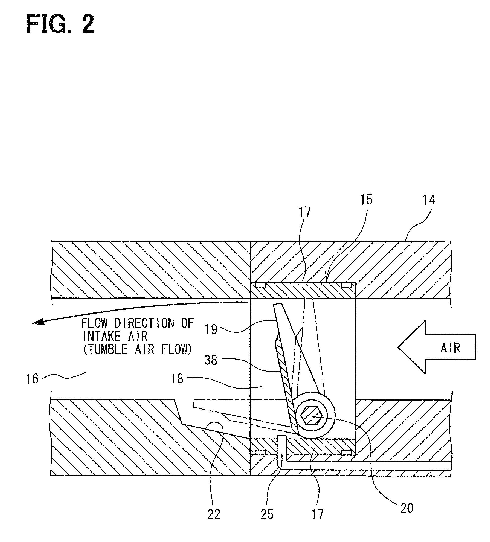
[0047]A general structure of an engine intake system will be explained with reference to FIG. 1. An internal combustion engine 11, for example, an in-line four cylinder engine, has four cylinders, that are first to fourth cylinders #1 to #4. An air flow meter (not shown) is provided in an intake pipe 12 (a main intake air passage) of the engine 11, in order to detect intake air amount. A surge tank 13 is provided at a downstream side of the air flow meter. Intake manifolds (branched intake air passages) 14 are connected to the surge tank 13, to supply the intake air into respective cylinders of the engine 11. Throttle valve units 15 are provided in each of the intake manifolds 14, to control the intake air amount to be supplied to the respective cylinders. Fuel injection valves (not shown) are provided adjacent to an intake port 16 of the respective cylinders, to inject fuel into the ...
second embodiment
[0118]The above first embodiment shows an example, in which the air ejector 27 is used. It is not necessary to positively use the PCV gas as the driving gas for the air ejector 27, in such an engine in which the amount of the PCV gas is small, or in such an arrangement in which the PCV gas is discharged into the intake pipe at the upstream side of the throttle valve 19 (adjacent to a fully closed position of the throttle valve 19).
[0119]According to such an arrangement, the air ejector 27 may be eliminated, but a structure according to a second embodiment shown in FIGS. 15 to 20 may be used. The second embodiment will be explained below.
[0120]According to the second embodiment, as shown in FIG. 15, is the negative pressure passage 36 of the brake booster 35 is connected to the negative pressure pipe 26, to which the communication passages 25 for the respective cylinders are converged, via a negative pressure control valve 51. A check valve 52 is provided in each of the communication...
third embodiment
[0141]In the above explained first and second embodiments, the cantilever type throttle valve 19 is used, wherein the throttle valve 19 has the shaft 20 at the lower side of the throttle valve unit is. According to the third embodiment shown in FIG. 21, however, a throttle valve 63 of a butterfly-valve type is used, wherein the throttle valve 63 has a shaft 62 at a center of a throttle valve unit 61.
[0142]In the third embodiment, a bore 66 of a spherical surface is formed at a lower surface of an air passage 65 of a housing 64 for the throttle valve unit 61, wherein the shape of the bore 66 (the spherical surface) is so formed to correspond to a shape of a lower end of the throttle valve 63. Accordingly, a space (a gap) between the lower end of the throttle valve 63 and the lower surface of the air passage 65 is closed by the bore 66, when the throttle valve 63 is in a predetermined opening degree (for example, 20 degrees) from its fully closed position. As a result, an air flow of ...
PUM
 Abstract
Description
Claims
Application Information
 - R&D
- Intellectual Property
- Life Sciences
- Materials
- Tech Scout
- Unparalleled Data Quality
- Higher Quality Content
- 60% Fewer Hallucinations
Browse by: Latest US Patents, China's latest patents, Technical Efficacy Thesaurus, Application Domain, Technology Topic, Popular Technical Reports.
© 2025 PatSnap. All rights reserved.Legal|Privacy policy|Modern Slavery Act Transparency Statement|Sitemap|About US| Contact US: help@patsnap.com


