
Starting system and method of internal combustion engine

a technology of internal combustion engine and starting system, which is applied in the direction of engine starters, electric control, instruments, etc., can solve the problems of reducing the service life of the starter motor and its peripheral parts, affecting the reliability and efficiency of the engine, and affecting the reliability of the engine. , to achieve the effect of improving the reliability and efficiency, and improving the quietness of the engin

Inactive Publication Date: 2009-05-21
TOYOTA JIDOSHA KK
View PDF6 Cites 9 Cited by
  • Summary
  • Abstract
  • Description
  • Claims
  • Application Information

AI Technical Summary

Benefits of technology

[0005]It is therefore an object of the invention to provide starting system and method of an internal combustion engine, for starting the engine with improved reliability and efficiency while assuring improved quietness of the engine.
[0007]In the starting system of the internal combustion engine according to the first aspect of the invention, the throttle device is operated to open the throttle valve to the throttle opening that is set based on the intake pressure during stopping of the engine. Upon a start of the engine, the fuel injecting means is actuated to inject the fuel into the cylinder that is judged as being in the expansion stroke based on the result of detection of the crank angle sensing means, and the igniting means is actuated to ignite the air / fuel mixture. With the throttle valve thus opened during idle running of the engine prior to its stop, fresh air is drawn into each cylinder for scavenging, resulting in an increase of the amount of oxygen in the cylinder, and the negative pressure in the cylinder is reduced so that the piston is stopped at an appropriate position. When the engine is subsequently started, therefore, the air / fuel mixture can be ignited and burned without fail, to provide certain driving force due to combustion of the mixture, thus enabling the engine to start with improved reliability and efficiency. Furthermore, since the throttle opening to which the throttle valve is opened during stopping of the engine is set based on the intake pressure, otherwise possible occurrence of unusual sound due to rapid inflow of air can be prevented, assuring improved quietness of the engine.
[0010]In the starting system of the internal combustion engine according to the second aspect of the invention, the throttle device is operated to open the throttle valve to the predetermined throttle opening at the throttle opening speed that is set based on the intake pressure during stopping of the engine. Upon a start of the engine, the fuel injecting means is actuated to inject the fuel into the cylinder that is judged as being in the expansion stroke based on the result of detection of the crank angle sensing means, and the igniting means is actuated to ignite the air / fuel mixture. With the throttle valve thus opened during idle running of the engine prior to its stop, fresh air is drawn into each cylinder for scavenging, resulting in an increase of the amount of oxygen in the cylinder, and the negative pressure in the cylinder is reduced so that the piston is stopped at an appropriate position. When the engine is subsequently started, therefore, the air / fuel mixture can be ignited and burned without fail, to provide certain driving force due to combustion of the mixture, thus enabling the engine to start with improved reliability and efficiency. Furthermore, since the throttle opening speed at which the throttle valve is opened during stopping of the engine is set based on the intake pressure, otherwise possible occurrence of unusual sound due to rapid inflow of air can be prevented, assuring improved quietness of the engine.
[0011]In the starting system according to the second aspect of the invention, the control means may set the throttle opening speed at which the throttle valve is opened during stopping of the engine, such that the throttle opening speed decreases as the intake pressure increases.

Problems solved by technology

With regard to these technologies, if it takes an undesirably long time to restart the engine, the driveability may deteriorate due to a delay in response to the driver's intention of starting, and it is therefore important to quickly restart the engine.
Generally, a starter motor is used for starting the engine, which makes it difficult to quickly restart the engine.
Furthermore, the above-described technologies require the engine to be frequently stopped and started in a repeated fashion, resulting in reduction of service life of the starter motor and its peripheral parts, and reduction of the amount of electric power charged in the battery due to excessive use of the battery.
However, if the throttle valve is suddenly opened while the engine is being stopped, upon meeting of engine stop conditions, from an operating condition (e.g., an idling state) in which the intake manifold vacuum is large, air rapidly flows into the intake pipe, causing a problem such as occurrence of unusual sound or noise.

Method used


Image

  • Starting system and method of internal combustion engine
  • Starting system and method of internal combustion engine
  • Starting system and method of internal combustion engine

Examples


first embodiment

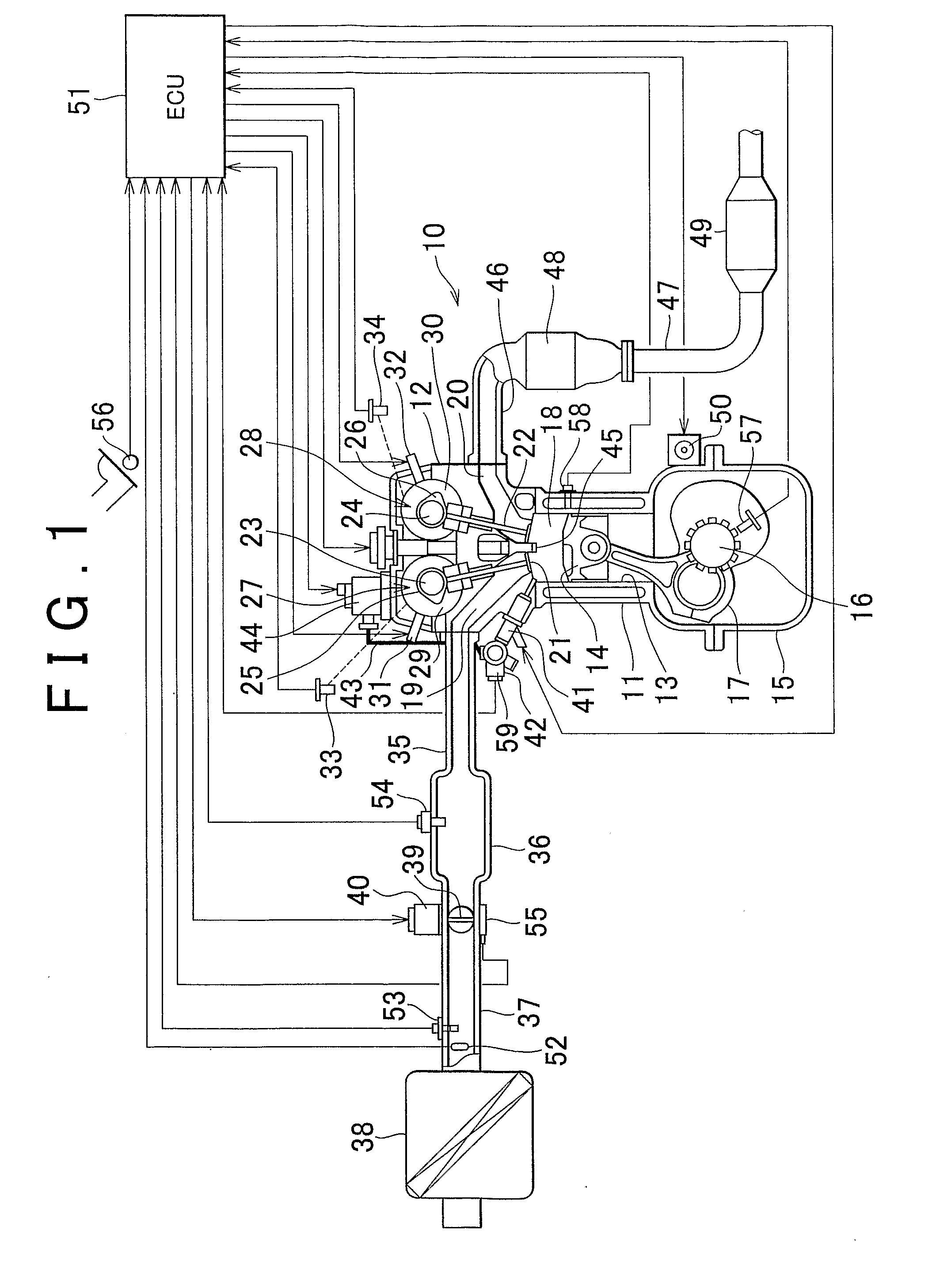
[0022]FIG. 1 schematically shows a starting system of an internal combustion engine constructed according to the first embodiment of the invention. FIG. 2 is a flowchart illustrating engine stop control and start control performed by the engine starting system of the first embodiment. FIG. 3 schematically shows the behavior of the pistons and valves in some cylinders, which is observed when the engine stops in the engine starting system of the first embodiment. FIG. 4 is a graph indicating the throttle opening with respect to the intake manifold vacuum sensed during stopping of the engine. FIG. 5 is a time chart indicating changes in the throttle opening and the pressure in the intake pipe during stopping of the engine in the engine starting system of the first embodiment.

[0023]The internal combustion engine to which the starting system of the first embodiment is applied is a four-cylinder engine 10 of direct in-cylinder injection type as shown in FIG. 1. The engine 10 includes a cy...

second embodiment

[0053]FIG. 6 is a flowchart illustrating engine stop control and start control performed by a starting system of an internal combustion engine as the second embodiment of the invention. FIG. 7 is a time chart showing the throttle opening speed and the pressure in the intake pipe observed during stopping of the engine in the engine starting system of the second embodiment. The whole construction of the engine starting system of this embodiment is substantially the same as that of the first embodiment as described above, and will be described with reference to FIG. 1. In the following description, the same reference numerals as used in the explanation of the first embodiment will be used for identifying structurally and / or functionally corresponding elements, of which detailed description will not be provided.

[0054]Like the engine starting system of the first embodiment as described above, the engine starting system of the second embodiment has the function of automatically stopping t...


PUM


Abstract

In a starting system of an internal combustion engine, an injector for injecting fuel directly into a combustion chamber and an ignition plug for igniting an air / fuel mixture in the combustion chamber are provided, and a throttle device is provided in an intake pipe. During stopping of the engine, the starting system operates the throttle device to open a throttle valve to a predetermined throttle opening at a throttle opening speed that is set based on the intake pressure. Upon a start of the engine, the starting system actuates the injector to inject the fuel into a cylinder that is in the expansion stroke, and actuates the ignition plug to ignite the mixture in the combustion chamber.

Description

TECHNICAL FIELD[0001]The invention relates to starting system and method of an internal combustion engine, in which fuel injection and ignition are performed in a cylinder that is in the expansion stroke, so as to start the engine by using combustion energy resulting from combustion of an air / fuel mixture formed in the expansion-stroke cylinder.BACKGROUND ART[0002]In recent years, various technologies for automatically stopping the engine while the vehicle is stopped in an idling state and automatically restarting the engine so as to smoothly start the vehicle have been proposed as methods for reducing or controlling exhaust emissions and improving the fuel economy. With regard to these technologies, if it takes an undesirably long time to restart the engine, the driveability may deteriorate due to a delay in response to the driver's intention of starting, and it is therefore important to quickly restart the engine. Generally, a starter motor is used for starting the engine, which m...

Claims


Application Information

Patent Timeline
IPC IPC(8): F02D41/06F02D17/00F02D29/02F02D41/04F02N9/02F02N99/00
CPCF02D11/10F02D41/0002F02D41/042F02D41/062F02D2011/102F02D2041/0092Y02T10/42F02D2200/0404F02D2200/0406F02N11/0814F02N99/006F02N2200/021F02D2041/0095Y02T10/40
Inventor KOJIMA, SUSUMU
Owner TOYOTA JIDOSHA KK
Learn More