
Carbon nanotubes for fuel cells, method for manufacturing the same, and fuel cell using the same

a technology of carbon nanotubes and fuel cells, applied in cell components, nanoinformatics, electrochemical generators, etc., can solve the problems of limited area where carbon nanotubes are grown, insufficient surface area of carbon carrier and electrical conductivity, and insufficient dispersion of catalysts in electrode backing layers, etc., to achieve the effect of improving efficiency

Inactive Publication Date: 2011-12-27
SAMSUNG SDI CO LTD
View PDF20 Cites 21 Cited by
  • Summary
  • Abstract
  • Description
  • Claims
  • Application Information

AI Technical Summary

Benefits of technology

The use of carbon nanotubes with uniformly distributed catalysts increases the reaction efficiency in fuel cells, simplifies the manufacturing process, and lowers production costs by directly integrating them into the fuel cell electrodes, resulting in improved performance and efficiency compared to conventional methods.

Problems solved by technology

However, the dispersion of the catalyst in the electrode backing layers is not uniform, and the surface area of the carbon carrier and electrical conductivity are not large enough.
In this method, the use of laser limits the area where carbon nanotubes are grown.
To be applied to fuel cells, an additional step of coating electrodes with a paste of the carbon nanotubes is required, which makes the overall fuel cell manufacturing process complicated.

Method used


Image

  • Carbon nanotubes for fuel cells, method for manufacturing the same, and fuel cell using the same
  • Carbon nanotubes for fuel cells, method for manufacturing the same, and fuel cell using the same
  • Carbon nanotubes for fuel cells, method for manufacturing the same, and fuel cell using the same

Examples


example 1

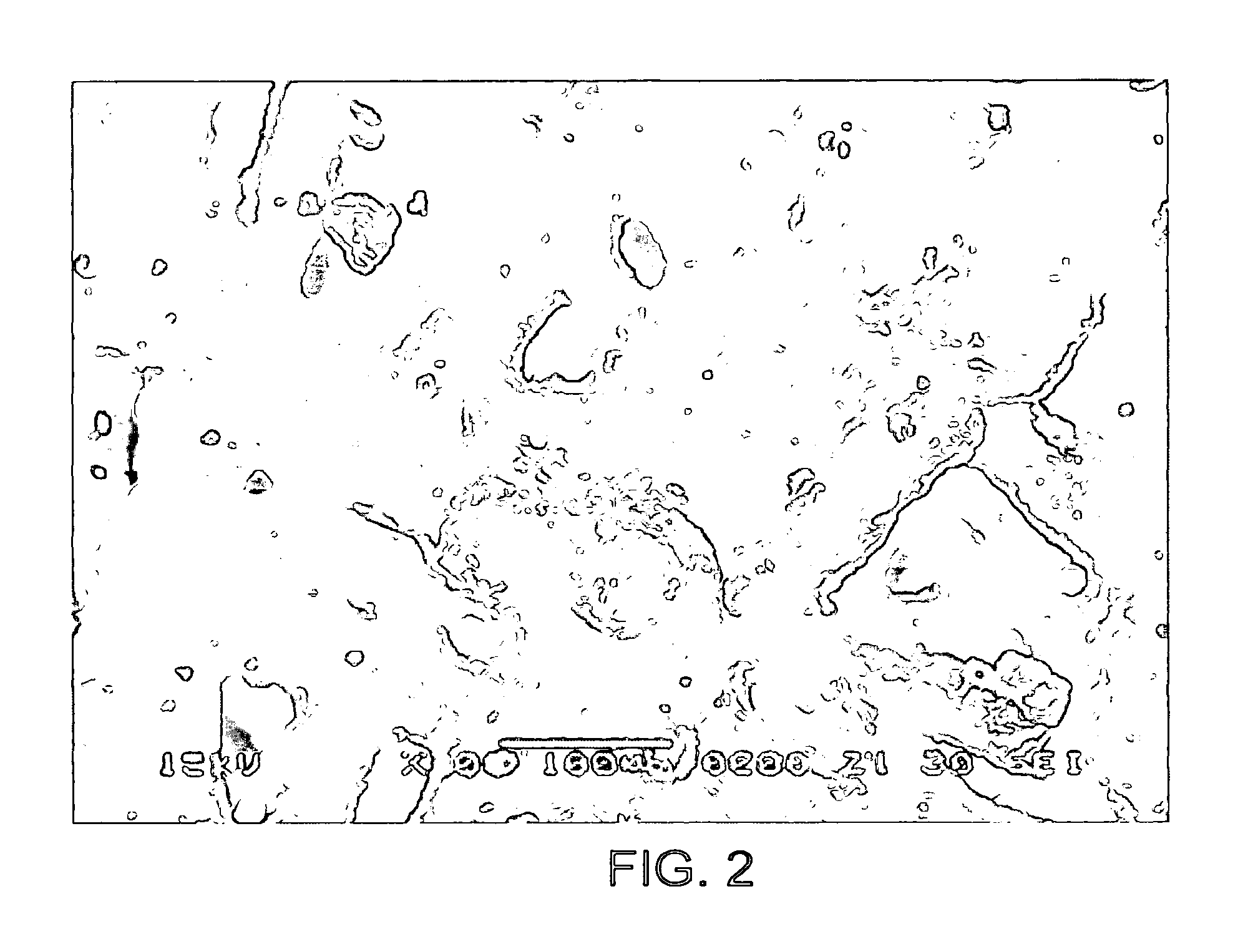
[0041]Platinum (Pt) as a metallic catalyst was dispersed over a water-proofed carbon paper serving as a carbon substrate for 1 minute by electrophoresis, and a uniform dispersion of the Pt particles was confirmed using scanning electron microscope (SEM)-energy dispersive spectroscopy (EDS). The result is shown in FIG. 2. The carbon substrate over which the Pt particles had been uniformly distributed was mounted in a quartz boat and placed at the center of a reactor. The reactor was purged with argon gas at 5000 sccm under atmospheric pressure while the temperature of the reactor was elevated to 500. When the temperature of the reactor reached 500, acetylene was supplied into the reactor as a carbon source gas at 10 sccm under atmospheric pressure for 60 minute to synthesize carbon nanotubes. Next, while argon gas was supplied into the reactor at 300 sccm under atmospheric pressure, the temperature of the carbon nanotubes were dropped to room temperature to provide carbon nanbtubes d...

example 2

[0042]Carbon nanotubes were synthesized in the same manner as in Example 1, except that Fe2O3 instead of Pt was used as the catalyst. As a result, carbon nanotubes doped with Fe particles uniformly to a degree of 2 mg / cm2 were obtained.

example 3

[0043]Branched carbon nanotubes were synthesized in the same manner as in Example 1, except that, after 10 minutes from the supply of the carbon source gas to allow carbon nanotubes to grow to some extent, hydrogen gas was supplied into the reactor at 50 sccm for 20 minutes. As a result, branched carbon nanotubes doped with the catalyst particles uniformly to a degree of 2 mg / cm2 were obtained.

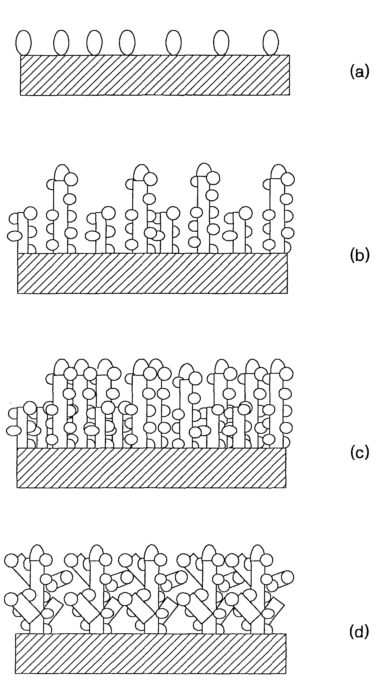
[0044]As described above, carbon nanotubes whose internal and external walls are uniformly doped with metallic catalyst particles having a diameter of a few nanometers according to the present invention, which are directly grown over a carbon substrate, have a wide specific surface area, especially when the carbon nanotubes are branched off, so that the carbon nanotubes according to the present invention maximize the reaction efficiency in an electrode when used for the electrode of a fuel cell. In addition, since the carbon nanotubes are directly grown over a carbon substrate that can be used...


PUM

PropertyMeasurementUnit
temperatureaaaaaaaaaa
room temperatureaaaaaaaaaa

Abstract

The internal and external walls of the carbon nanotubes are doped with nano-sized metallic catalyst particles uniformly to a degree of 0.3-5 mg / cm2. The carbon nanotubes are grown over a carbon substrate using chemical vapor deposition or plasma enhanced chemical vapor deposition. Since the carbon nanotubes have a large specific surface area, and metallic catalyst particles are uniformly distributed over the internal and external walls thereof, the reaction efficiency in an electrode becomes maximal when the carbon nanotubes are used for the electrode of a fuel cell. The carbon nanotubes fabricated using the method can be applied to form a large electrode. The carbon nanotubes grown over the carbon substrate can be readily applied to an electrode of a fuel cell, providing economical advantages and simplifying the overall electrode manufacturing process. A fuel cell using as the carbon nanotubes for its electrode provides improved performance.

Description

[0001]This application is a divisional of U.S. patent application Ser. No. 10 / 601,872, filed Jun. 24, 2003 allowed as U.S. Pat. No. 7,585,584.BACKGROUND OF THE INVENTION[0002]This application claims priority from Korean Patent Application No. 2002-44631, filed on Jul. 29, 2002, in the Korean Intellectual Property Office, the disclosure of which is incorporated herein in its entirety by reference.[0003]1. Field of the Invention[0004]The present invention relates to carbon nanotubes, and more particularly, to carbon nanotubes for fuel cells, which are directly grown over a carbon substrate and whose internal and external walls are uniformly doped with metallic catalyst particles, and a method for fabricating the carbon nanotubes, and a fuel cell using the carbon nanotubes for an electrode.[0005]2. Description of the Related Art[0006]Recently, with growing concerns about the environment and the exhaustion of energy resources, and the commercialization of fuel cell automobiles, there is...

Claims


Application Information

Patent Timeline
Patent Type & Authority Patents(United States)
IPC IPC(8): C01B31/00D01F9/12B82B3/00B82B1/00B82Y30/00B82Y40/00B82Y99/00C01B31/02C23C14/18C23C16/26H01M4/86H01M4/88H01M4/90H01M4/92H01M4/96H01M8/10
CPCB82Y30/00B82Y40/00C01B31/0233H01M4/8605H01M4/9083H01M4/926Y10S977/743Y02E60/50Y10S977/70Y10S977/843Y10S977/847Y10S977/701Y10S977/72H01M2008/1095C01B32/162B82B1/00B82B3/00B82Y10/00
Inventor CHOI, WON-BONGCHU, JAE-UKPAK, CHAN-HOCHANG, HYUK
Owner SAMSUNG SDI CO LTD
Learn More