
Thin-film deposition and recirculation of a semi-conductor material

a technology of semi-conductor materials and thin-film deposition, which is applied in the direction of photovoltaic energy generation, ion implantation coatings, coatings, etc., can solve the problems of loose dust formation, minimize the vapor phase nucleation of semiconductor materials, and maximize the quality of thin-film formation , the effect of minimizing production costs

Inactive Publication Date: 2011-12-13
CALYXO
View PDF16 Cites 2 Cited by
  • Summary
  • Abstract
  • Description
  • Claims
  • Application Information

AI Technical Summary

Benefits of technology

[0011]Concordant and congruous with the present invention, a thin-film photovoltaic material deposition process adapted to minimize the vapor phase nucleation of the semiconductor material during the deposition process to maximize the quality of the thin-film formed on a substrate, while minimizing the cost of production thereof, has surprisingly been discovered.
[0015]In one embodiment of the invention, a process for coating a substrate at atmospheric pressure, comprises the steps of vaporizing a controlled mass of semiconductor material at substantially atmospheric pressure within a heated inert gas stream to create a fluid mixture having a temperature above the condensation temperature of the semiconductor material; directing the fluid mixture at substantially atmospheric pressure onto the substrate, the substrate having a temperature below the condensation temperature of the semiconductor material thereby depositing a layer of the semiconductor material onto a surface of the substrate; extracting undeposited semiconductor material; circulating the undeposited semiconductor material into the fluid mixture having a temperature above the condensation temperature; and repeating the steps of vaporizing, directing, depositing, extracting, and circulating to minimize a loss of the undeposited semiconductor material.

Problems solved by technology

However, when the vapor concentration of the material becomes higher than the supersaturation level of the vapor at the operating temperature and pressure of the process, loose dust may form due to vapor phase nucleation of the semiconductor material.

Method used


Image

  • Thin-film deposition and recirculation of a semi-conductor material
  • Thin-film deposition and recirculation of a semi-conductor material
  • Thin-film deposition and recirculation of a semi-conductor material

Examples


Embodiment Construction

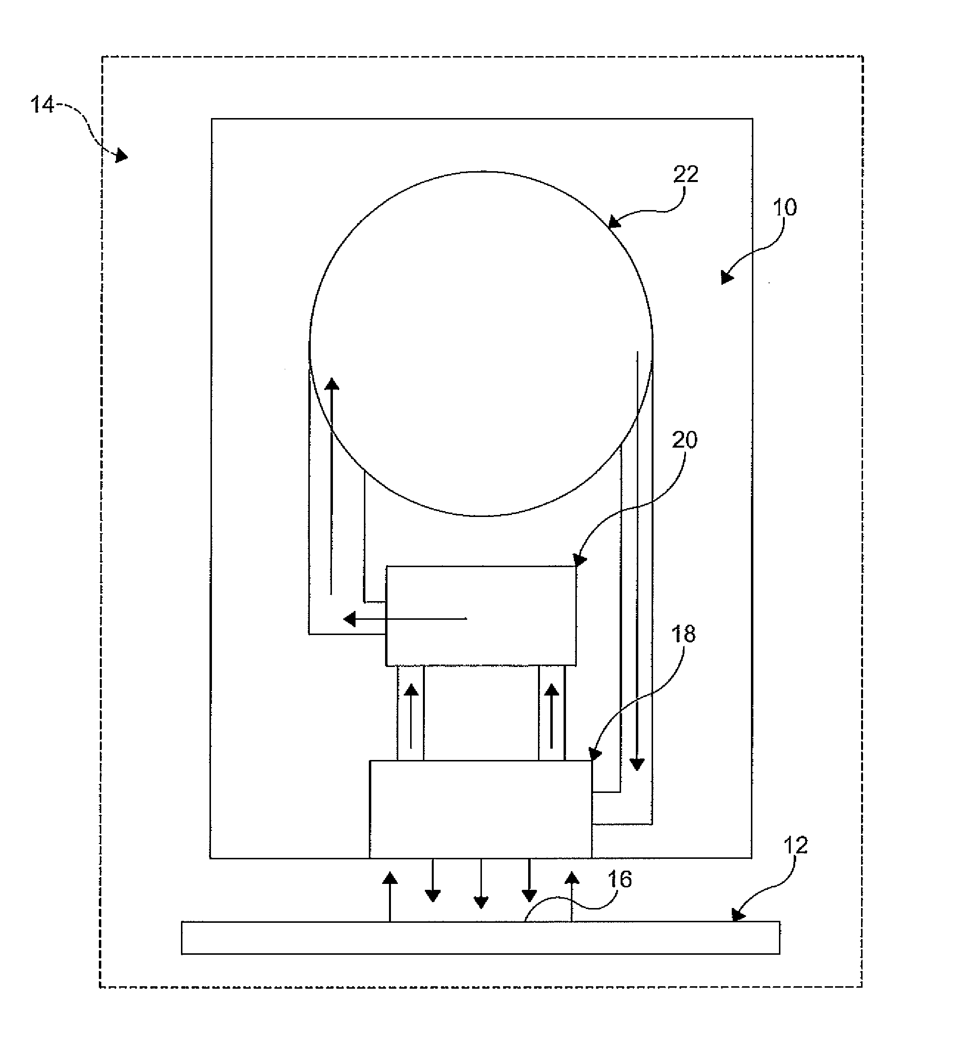
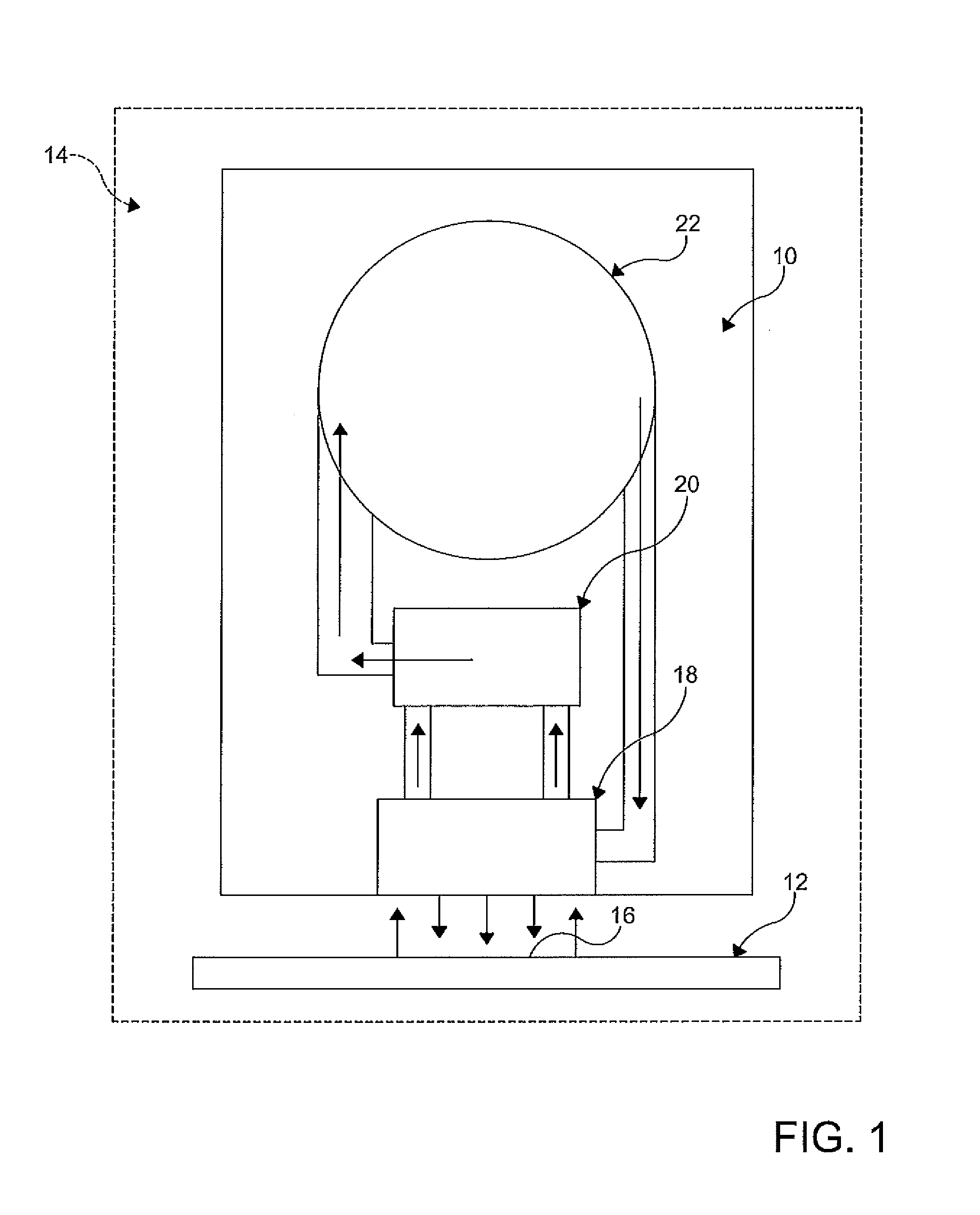
[0019]Referring to FIG. 1, there is shown a recirculation system 10 for coating a surface of a substrate 12 with a film of semiconductor material, such as cadmium telluride and cadmium sulfide, example, at atmospheric pressure. The recirculation system 10 is preferably maintained in a heated inert gas temperature zone 14 above ambient temperature and at atmospheric pressure.

[0020]A known quantity of random sized CdS or CdTe particles is placed into a heated vessel 20 within the system 10. The particles may have any size, but favorable results have been obtained with particles having a size range from about 1 cm diameter to about 5 cm diameter, In the embodiment shown in FIG. 1, the heated vessel 20 is a heated bed. The heated vessel 20 is designed so that a fluid may be recirculated therethrough, and heated to a desired and controlled temperature as it passes therethrough. The desired temperature is a temperature below the temperature at which the semiconductor material will vaporiz...


PUM

PropertyMeasurementUnit
diameteraaaaaaaaaa
temperatureaaaaaaaaaa

Abstract

A process for coating a substrate at atmospheric pressure is disclosed, the process comprising the steps of vaporizing a mass of semiconductor material within a heated inert gas stream to create a fluid mixture having a temperature above the condensation temperature of the semiconductor material, directing the fluid mixture at the substrate, the substrate having a temperature below the condensation temperature of the semiconductor material thereby depositing a layer of the semiconductor material onto a surface of the substrate, extracting undeposited semiconductor material; and circulating the undeposited semiconductor material into the fluid mixture having a temperature above the condensation temperature.

Description

CROSS-REFERENCE TO RELATED APPLICATION[0001]This application claims the benefit of priority of U.S. Provisional Patent Application Ser. No. 61 / 120,629 filed on Dec. 8, 2008 hereby incorporated herein by reference.FIELD OF THE INVENTION[0002]The present invention relates generally to the deposition of a vaporized chemical material on a substrate, and more particularly to a process for depositing a recirculated vaporized chemical material and inert gas mixture on a substrate at atmospheric pressure.BACKGROUND OF THE INVENTION[0003]Chemical vapor deposition processes such as pyrolytic processes and hydrolytic processes are well known in the art of coating substrates. The physical characteristics of the coating reactants utilized in such processes may be a liquid, a vapor, or a solid dispersed in gaseous mixtures, aerosols, or vaporized or vaporous coating reactants dispersed in gaseous mixtures.[0004]In the process of deposition of a vaporized chemical compound on a glass substrate in ...

Claims


Application Information

Patent Timeline
Patent Type & Authority Patents(United States)
IPC IPC(8): H01L21/203
CPCC23C14/0629C23C14/228C23C14/24C23C14/246H01L31/073H01L31/0749H01L31/1872H01L21/02557Y02E10/543H01L21/02568Y02E10/541H01L21/02562Y02P70/50
Inventor KORMANYOS, KENNETH R.
Owner CALYXO
Learn More