
Quick-tightening system for cycle with tightening torque control

a technology of torque control and tightening system, which is applied in the direction of screws, nuts, bolts, etc., can solve the problems of not enabling a good control of the tightening force, possible safety problems, and the risk of skewer rupture or breakage of another element of the device, so as to achieve sufficient mechanical strength, reduce weight, and low density

Active Publication Date: 2011-12-13
THULE SWEDEN AB
View PDF12 Cites 9 Cited by
  • Summary
  • Abstract
  • Description
  • Claims
  • Application Information

AI Technical Summary

Benefits of technology

The invention provides a quick-release system for a cycle, including a skewer and an end support element, with a tightening sub-assembly and an actuation sub-assembly capable of transmitting torque to the tightening sub-assembly. The system includes a torque limiting mechanism that limits the torque transmitted by the actuation sub-assembly to the tightening sub-assembly, starting from a limiting value or a preset range of tightening torages. The system can be easily adjusted to different tightening torages and can be used with different types of cycle devices. The invention also provides a quick-release device that includes a torque limiting mechanism and a torsional stress recovery mechanism to ensure optimal tightening against the tightening surfaces and to prevent damage to the device.

Problems solved by technology

These devices pose a number of problems.
Initially, they do not enable a good control of the tightening force, which can vary substantially depending upon the adjustment of the center distance, by the user, by means of the adjustment nut of the quick-release mechanism.
A center distance adjusted to be too long at the outset can produce an insufficient tightening and thus cause a possible safety problem.
An adjusted center distance adjusted to be too short, on the contrary, can cause an axial tension force on the skewer that is too substantial, and thus a risk of rupture of the skewer or breakage of another element of the device.
A too substantial tension force also produces compression forces on the hub bearings.
As a result, the bearings may be compressed and therefore damaged, thus causing substantial friction in the hub.
Moreover, a device of this type is not easy to use, and the user has to proceed by trial and error in adjusting the center distance in order to achieve the correct tightening.
The tightening magnitudes can vary substantially, resulting in risks of loosening in the case of insufficient tightening or, conversely, of failure / breakage of the skewer, in the case of excessive tightening.
Oversizing the elements and / or using light-weight materials such as titanium is expensive.
Another problem associated with a device of this type comes from the difficulty of obtaining a correct orientation of the lever at the end of the tightening and the correct tightening force at the same time.
However, this device does not improve the control of the tightening force.
All of the problems mentioned in relation to the lack of control of the tightening force thus subsist in this device.
However, although it provides an indication of the tightening value, such a device does not entirely solve the problems associated with excessive or insufficient tightening of the device.

Method used


Image

  • Quick-tightening system for cycle with tightening torque control
  • Quick-tightening system for cycle with tightening torque control
  • Quick-tightening system for cycle with tightening torque control

Examples


example

[0168]The following table shows a comparison of the characteristics of various types of possible skewers for the device of the invention, which are manufactured using various materials: high strength steel (HR), standard steel, TA6V titanium alloy, 7349 aluminum alloy 7349, 7349 aluminum alloy with higher strength and magnesium alloy.

[0169]The values are given for a skewer that can resist a maximal traction force F of 10000 Newtons.

[0170]

Max. F 10000HS SteelSteelTA-6V70757349MgAl8ZnRm1400900980500700340Density7.87.84.552.82.81.8Rm / d179.49115.38215.38178.57250188.89Cross7.1411.1110.202014.2929.41section(mm2)Diameter3.023.763.605.054.266.12(mm)Mass / m55.7186.6746.43564052.94Mass / 7349139%217%116%140%100%132%Cost / kg11406815Machin-00−−+++ability

[0171]The table shows that aluminum alloys represent an advantageous compromise in terms of low weight, low cost, and good machinability. Other types of skewers can be used in the invention, with certain disadvantages however associated with weight...


PUM


Abstract

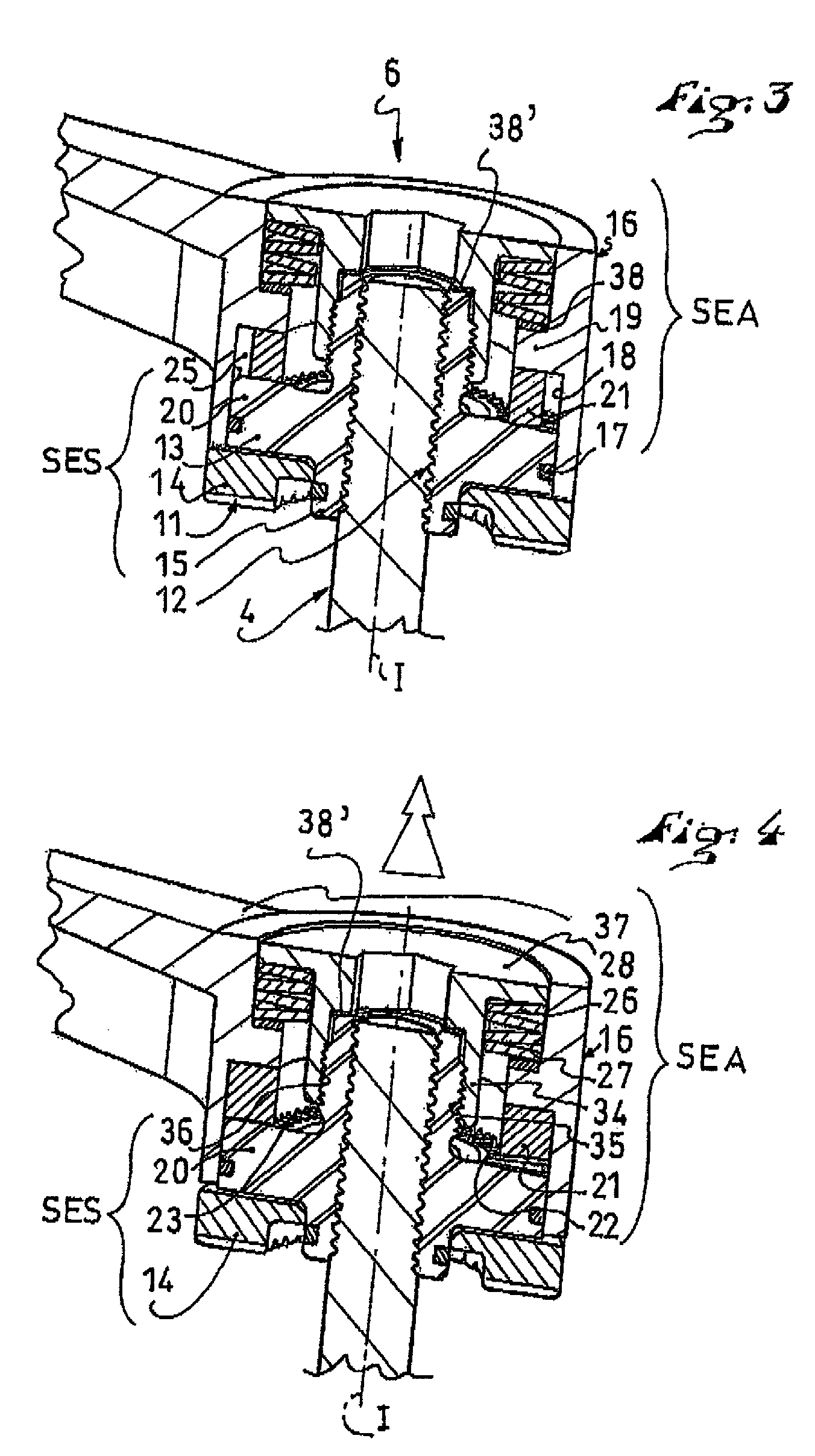
A quick-release system for a quick-release device, in particular for a cycle, such as a bicycle, the device being of the type including an axially extending skewer and an end support element mounted on a first end of the skewer adapted to be supported on a first tightening surface of the cycle. The quick-release system includes a tightening sub-assembly including a support surface and an actuation sub-assembly including a movable actuating mechanism, capable of axial rotation around the skewer and configured to transmit a tightening torque to the tightening sub-assembly when the device is being tightened. The system includes tightening torque limiting mechanism making it possible to limit the torque transmitted by the actuation sub-assembly to the tightening sub-assembly.

Description

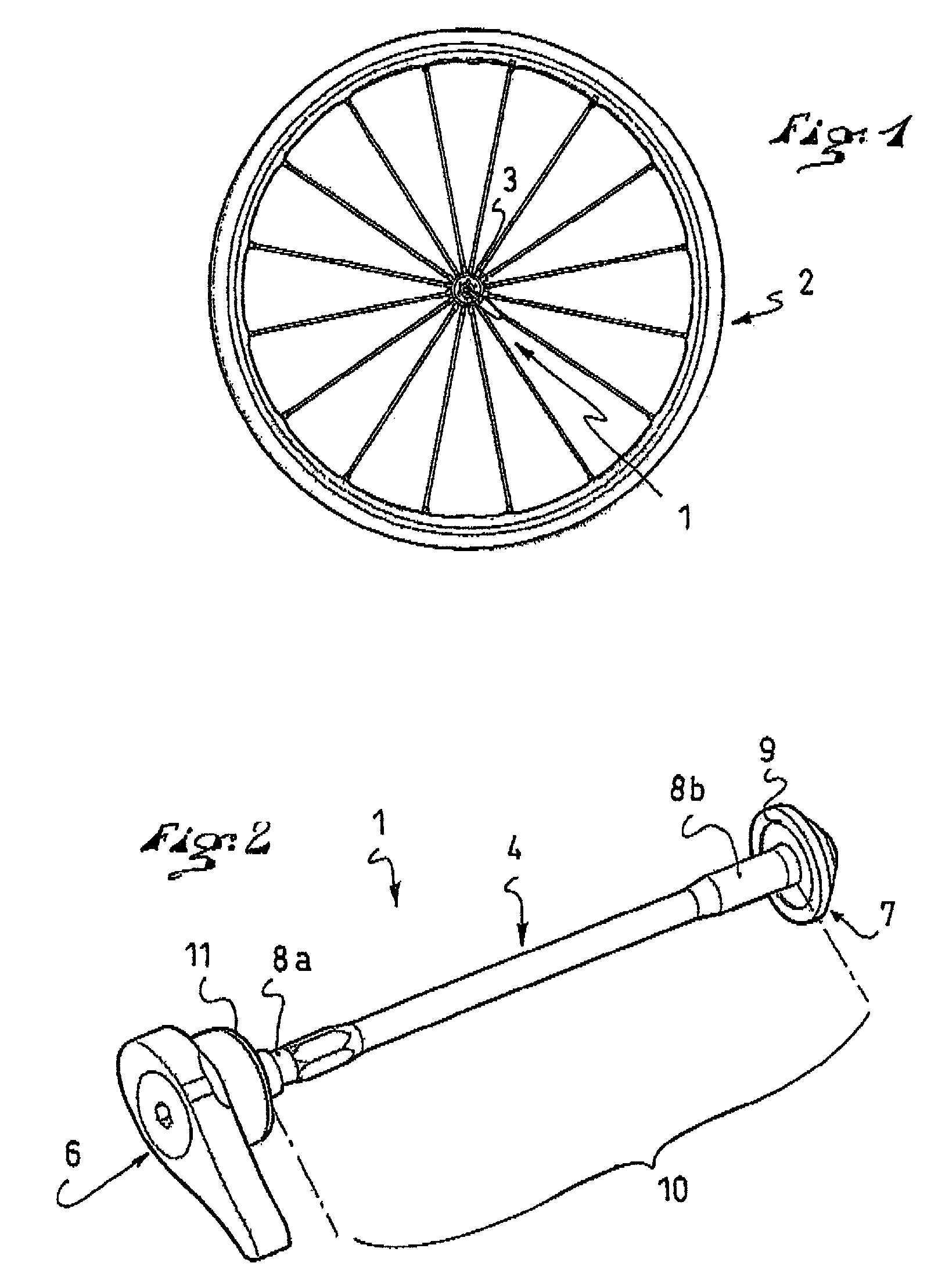
CROSS-REFERENCE TO RELATED APPLICATION[0001]This application claims priority under 35 U.S.C. §119 of French Patent Application No. 07 08577, filed on Dec. 10, 2007, the disclosure of which is hereby incorporated by reference thereto in its entirety.BACKGROUND OF THE INVENTION[0002]1. Field of the Invention[0003]The present invention relates to a quick-release system, in particular for a cycle. The invention also relates to a complete quick-release device, also commonly called “quick-release axle”, and to a wheel including such a device.[0004]2. Description of Background and Other Information[0005]In the field of cycles, it is known to use quick-release devices to assemble a component on a portion of the cycle quickly, such as a wheel to a fork, for example. These devices eliminate the need to use special tools, such as wrenches or the like. The quick-release devices can be used on a front wheel as well as on a rear wheel of a bicycle. The fastening device can also be used to secure ...

Claims


Application Information

Patent Timeline
Patent Type & Authority Patents(United States)
IPC IPC(8): B60B35/00
CPCB62K25/02F16B39/24F16B31/028B62K2206/00F16B35/042
Inventor MERCAT, JEAN-PIERREVEUX, JEAN-LUCNORMAND, JOSEPH
Owner THULE SWEDEN AB
Learn More