
Methods and apparatuses for removal and transport of thermal energy

a technology of thermal energy and methods, applied in the direction of lighting and heating apparatus, machines/engines, nuclear elements, etc., can solve the problems of toxic, self-ignition, chemical substances used in hydrogen production using one of several thermochemical cycles, etc., and achieve the effect of minimal energy loss

Active Publication Date: 2011-12-06
STC UNM
View PDF12 Cites 6 Cited by
  • Summary
  • Abstract
  • Description
  • Claims
  • Application Information

AI Technical Summary

Benefits of technology

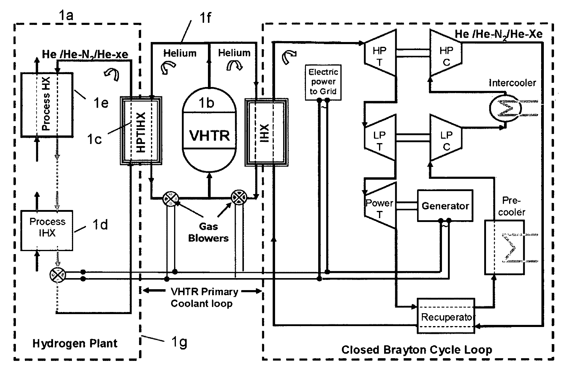
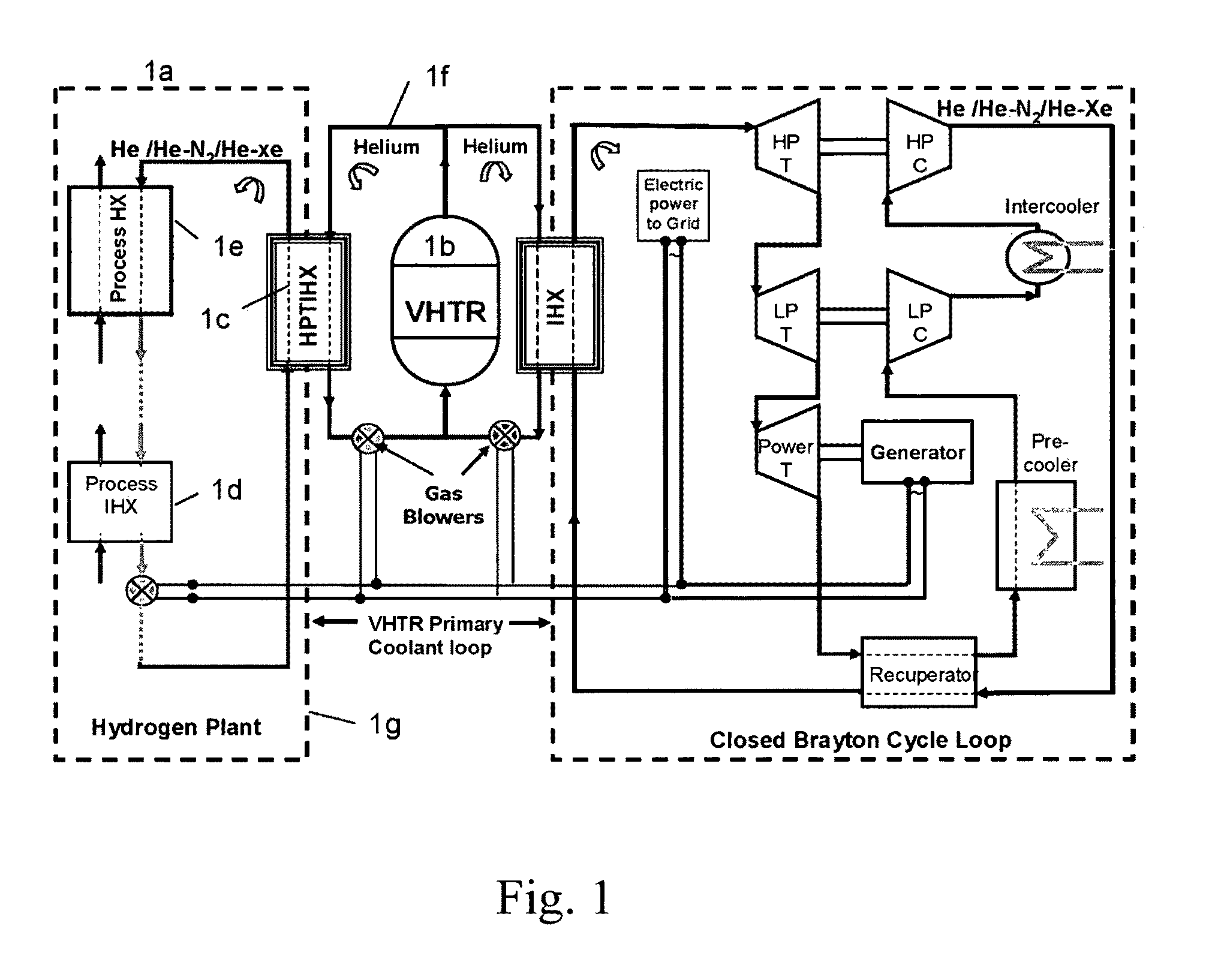
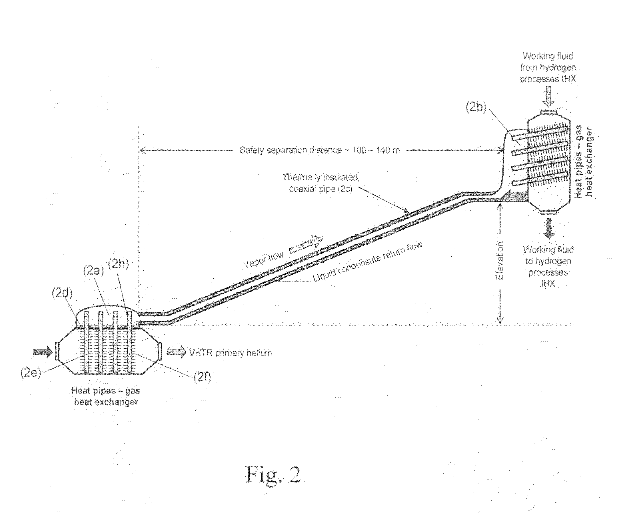
The patent describes an apparatus and method for removing and transporting a large amount of heat from a heat source to a remote location. The apparatus uses a hybrid heat pipes / thermosyphon intermediate heat exchanger to connect the heat source to the remote location without any single point failure. The method involves using heat pipes to transfer the heat from the heat source to a shallow pool of working liquid, which is then evaporated and transported through insulated pipes to the remote location. The working liquid is then condensed and returned back to the shallow pool for reuse. This technology allows for efficient and safe transfer of heat from a heat source to a remote location with minimal energy loss.

Problems solved by technology

The chemicals used for the production of hydrogen using one of several thermochemical cycles are very corrosive, toxic and may self ignite; let alone the self ignition of the hydrogen should it accidentally mix with air or oxygen above certain concentrations.

Method used


Image

  • Methods and apparatuses for removal and transport of thermal energy
  • Methods and apparatuses for removal and transport of thermal energy
  • Methods and apparatuses for removal and transport of thermal energy

Examples


Embodiment Construction

[0010]Heat pipes and thermosyphons are passive energy transport devices which do not require any active pumping of their working fluid, and take advantage of the large latent heat of vaporization of their working fluid for removing and transporting the heat at high rates from the heated section and releasing it in the cooled section. The heated and cooled sections of a heat pipe and a thermosyphon could be separated by a long distance, depending on the application and design. While the condensation section of a thermosyphon needs to be elevated relative to the evaporation section, in a heat pipe there is no such restriction. The hydrostatic head between the condensation and evaporation sections of a thermosyphon drives the liquid condensate back to the evaporation section and overcomes the pressure losses in the liquid film flow on the inside of the thermosyphon wall and in the counter current vapor flow from the evaporation to the condensation section. The heat pipes use a thin wic...


PUM


Abstract

Methods and apparatuses are provided for the removal and transportation of thermal energy from a heat source to a distant complex for use in thermochemical cycles or other processes. In one embodiment, an apparatus includes a hybrid heat pipes / thermosyphon intermediate heat exchanger (HPTIHX) system that is divided into three distinct sections, namely: an evaporation chamber, a condensation chamber, and a working fluid transport section of liquid and vapor counter-current flows.

Description

CROSS REFERENCE TO RELATED APPLICATIONS[0001]This application claims priority from U.S. Provisional Patent Application Ser. No. 60 / 930,059, which was filed on May 14, 2007, and which is incorporated by reference herein.TECHNICAL FIELD[0002]The present invention generally relates to methods and apparatuses for the passive removal and transfer of thermal energy from a heat source to a distant complex where this energy can be used, and more particularly relates to methods and apparatuses for the passive removal and transfer of thermal energy from a Very High Temperature Reactor to a distant hydrogen production complex of a Next Generation Nuclear Plant.BACKGROUND[0003]Energy is in great demand in today's society. Numerous heat generation sources can be used to harvest thermal energy. This energy may be converted into electricity or stored in a fuel through thermochemical cycles or other processes. For example, thermal energy from a nuclear reactor can be used to generate electricity an...

Claims


Application Information

Patent Timeline
Patent Type & Authority Patents(United States)
IPC IPC(8): F01K3/18
CPCF28D15/0233F28D15/0266F28D15/0275F28D15/04F28D2021/0054
Inventor EL-GENK, MOHAMED S.TOURNIER, JEAN-MICHEL
Owner STC UNM
Learn More