
Apparatus and method for detection, location, and identification of gamma sources

a technology of gamma source and detector, applied in the field of compact scintillation radiation detector, can solve the problems of lack of capability to quickly determine the location of the radiation source, lack of current information provided, insufficient in both routine inspection and other devices, known as compton cameras, capable of gamma ray azimuth detection, etc., to achieve reliable operation, high light yield, and precise energy resolution

Inactive Publication Date: 2011-11-29
SPACE MICRO A CORP OF DELAWARE
View PDF5 Cites 25 Cited by
  • Summary
  • Abstract
  • Description
  • Claims
  • Application Information

AI Technical Summary

Benefits of technology

"The present invention is about an apparatus and method for detecting and determining the source azimuth of gamma radiation from a set of radioisotopes. The apparatus includes at least two scintillation crystals placed at angular offsets to each other, with one crystal having a different axis of detection. Each crystal produces an electrical signal when it detects gamma rays. The signals are processed to determine the intensity and likely source azimuth of the detected radiation. The apparatus can also include GPS and compass sensors to track the position and orientation of the apparatus. The invention allows for the detection and determination of gamma rays from various radioisotopes sources in a handheld device."

Problems solved by technology

The United States government has identified a vital need of law enforcement, first responder and military staff responsible for detecting and responding to radiological threats to the United States to advance the state of the art of available omni-directional radiation detection devices, such as radiation portals and hand-held devices which are sensitive enough to detect many threats, but lack the capability to rapidly determine the location of the radiation source.
This problem is complicated by the fact that the terrestrial environment of concern includes significant naturally occurring radioactive material (NORM) and legitimate medical and industrial sources, which camouflage a threat source.
Additionally the threat source will often be present in a scatter rich environment further masking the direction and energy of the source.
The current information provided may be ambiguous and inadequate in both routine inspection and live threat response scenarios given that the main goal is to find the radiation source or sources quickly to determine the risk level and the appropriate response.
Still other devices, known as Compton cameras, while capable of gamma ray azimuth detection, cannot meet the above requirements.
However, Compton cameras currently are laboratory devices too large and cumbersome for use as set forth above.

Method used


Image

  • Apparatus and method for detection, location, and identification of gamma sources
  • Apparatus and method for detection, location, and identification of gamma sources
  • Apparatus and method for detection, location, and identification of gamma sources

Examples


Embodiment Construction

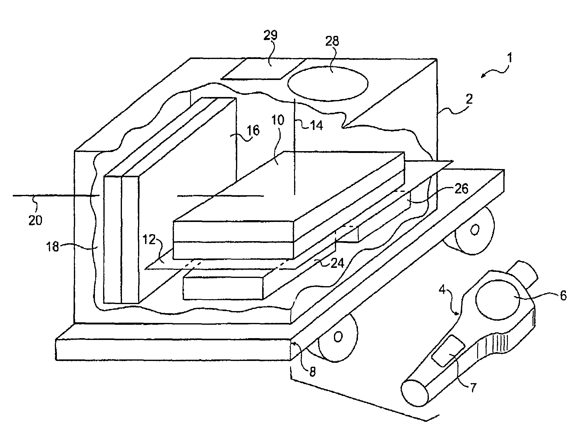
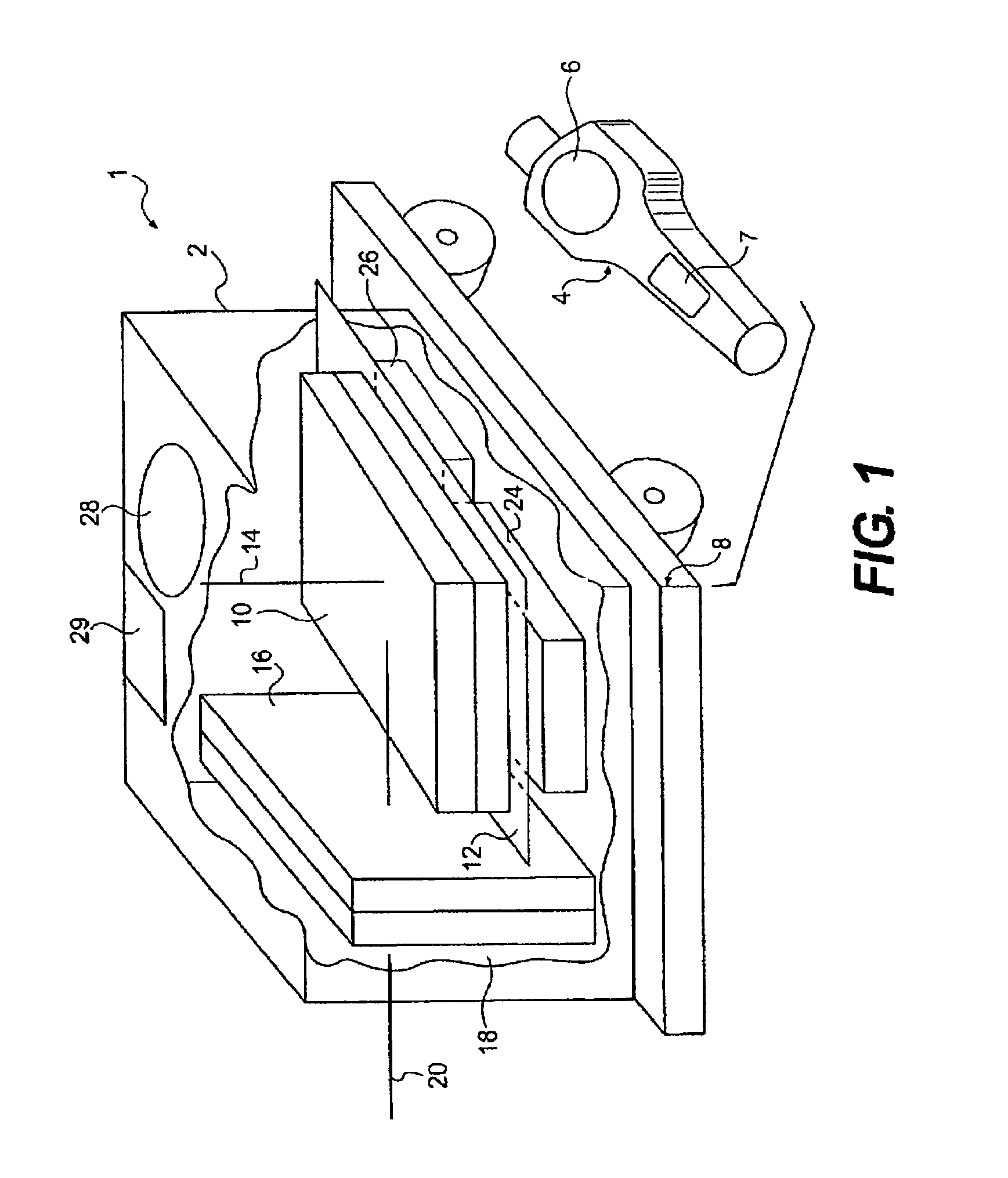
[0038]FIG. 1 is a perspective illustration of a detector instrument 1 constructed in accordance with an embodiment of the present invention. In one form, the detector instrument 1 will detect azimuth of a gamma radiation source. In a further embodiment, both azimuth and elevation may be determined in order to provide a three dimensional representation of location of the gamma source. Additionally, as further described below, energy spectra signatures of sources may be resolved in order to identify one or more radiation sources. The detector instrument 1 may be self-contained in a housing 2. Optionally, the detector instrument 1 may further comprise a remote control unit 4. In the present illustration, the remote control unit 4 comprises a display 6 and a user interface 7. The user interface 7 may comprise switches and other control means. Commonly, the remote control unit 4 will communicate with the housing 2 by a radio frequency (RF) link. Other or additional forms of communication...


PUM


Abstract

An apparatus for detecting and determining a source azimuth for gamma radiation includes at least two scintillation crystals at angular offsets and directed toward a common plane of detection, photodetectors adjacent to each of the scintillation crystals for converting the light response of the scintillation crystals into distinct electrical signals, and a digital processing system configured to analyze spectral data from each electrical signal produced for each crystal. The digital processing system monitors a finite number of spectral windows corresponding to a selected set of radioisotopes, and uses one or more of the electrical signals to determine a signal intensity and a likely source azimuth for a detected radioisotope in the plane of detection. Another scintillation crystal directed outside of the common plane of detection may be used for three-dimensional detection. Related methods for detection and location of gamma ray sources are discussed.

Description

CROSS-REFERENCE TO RELATED APPLICATIONS[0001]This application claims the benefit of U.S. Provisional Patent Application No. 60 / 812,894 filed Jun. 13, 2006, the contents of which are hereby incorporated by reference in their entirety.STATEMENT REGARDING FEDERALLY SPONSORED RESEARCH OR DEVELOPMENT[0002]The captioned invention was developed under United States of America Department of Defense Small Business Innovation Research contract NBCHC060045.BACKGROUND OF THE INVENTION[0003]1. Field of the Invention[0004]The present subject matter relates generally to radiation detection devices, and in particular to compact scintillation radiation detector ensembles that enable detection, identification and azimuth location of a radiation source in a single embodiment.[0005]2. Related Art[0006]The United States government has identified a vital need of law enforcement, first responder and military staff responsible for detecting and responding to radiological threats to the United States to adva...

Claims


Application Information

Patent Timeline
Patent Type & Authority Patents(United States)
IPC IPC(8): G01T1/00
CPCG01T1/20G01V5/0075G01V5/26
Inventor WINSO, JAMES HFENNELL, MICHAEL D
Owner SPACE MICRO A CORP OF DELAWARE
Learn More