
Transmission for vehicle

a technology for transmission and vehicles, applied in the direction of gearing control, gearing elements, gearing, etc., can solve the problems of increasing engagement noise, causing engagement noise, and relatively large speed between the shifter and the gear to be engaged with the shifter, so as to effectively and prevent an increase in engagement noise

Active Publication Date: 2011-11-08
HONDA MOTOR CO LTD
View PDF10 Cites 7 Cited by
  • Summary
  • Abstract
  • Description
  • Claims
  • Application Information

AI Technical Summary

Benefits of technology

[0010]In accordance with a second aspect of the present invention, the transmission for the vehicle further includes a shift fork for rotatably retaining the shifter; a shift drum having a lead groove on the outer circumference for engaging the shift fork; and a shift drum center rotating with the shift drum; wherein the feed mechanism has a shifting motor and rotationally drives the shift drum center by a predetermined angle according to the operation of the shifting motor; and the feed mechanism is configured to reduce the rotational speed of the shift drum center in the neutral condition, or to cause the rotation of the shift drum center to have a single stopping action in the neutral condition during the sliding operation of the shifter in changing the established condition of the gear trains.
[0028]According to the tenth aspect of the present invention, in sliding the shifter to change the established condition of the gear trains, the intermittent feed mechanism functions to bring the pawl into engagement with the engaging recess, thereby once stopping the rotation of the shift drum. Accordingly, the timing of engagement of the shifter to the gear of the selected gear train can be retarded, so that a difference in speed between the shifter and the gear to be engaged with the shifter can be relatively reduced to thereby more effectively prevent an increase in engagement noise.

Problems solved by technology

Accordingly, in sliding a shifter to change the established condition of the gear trains, a difference in speed between the shifter and a gear to be engaged with the shifter is relatively large, causing an increase in engagement noise.
Particularly in such a vehicle that a shift position is automatically changed according to an upshift or downshift operation and that preliminary shifting is performed during running at any shift position, there is a possibility that a large engagement noise may be produced not in concert with the operation by an operator, so that the operator may feel discomfort in shifting.

Method used


Image

  • Transmission for vehicle
  • Transmission for vehicle
  • Transmission for vehicle

Examples


Embodiment Construction

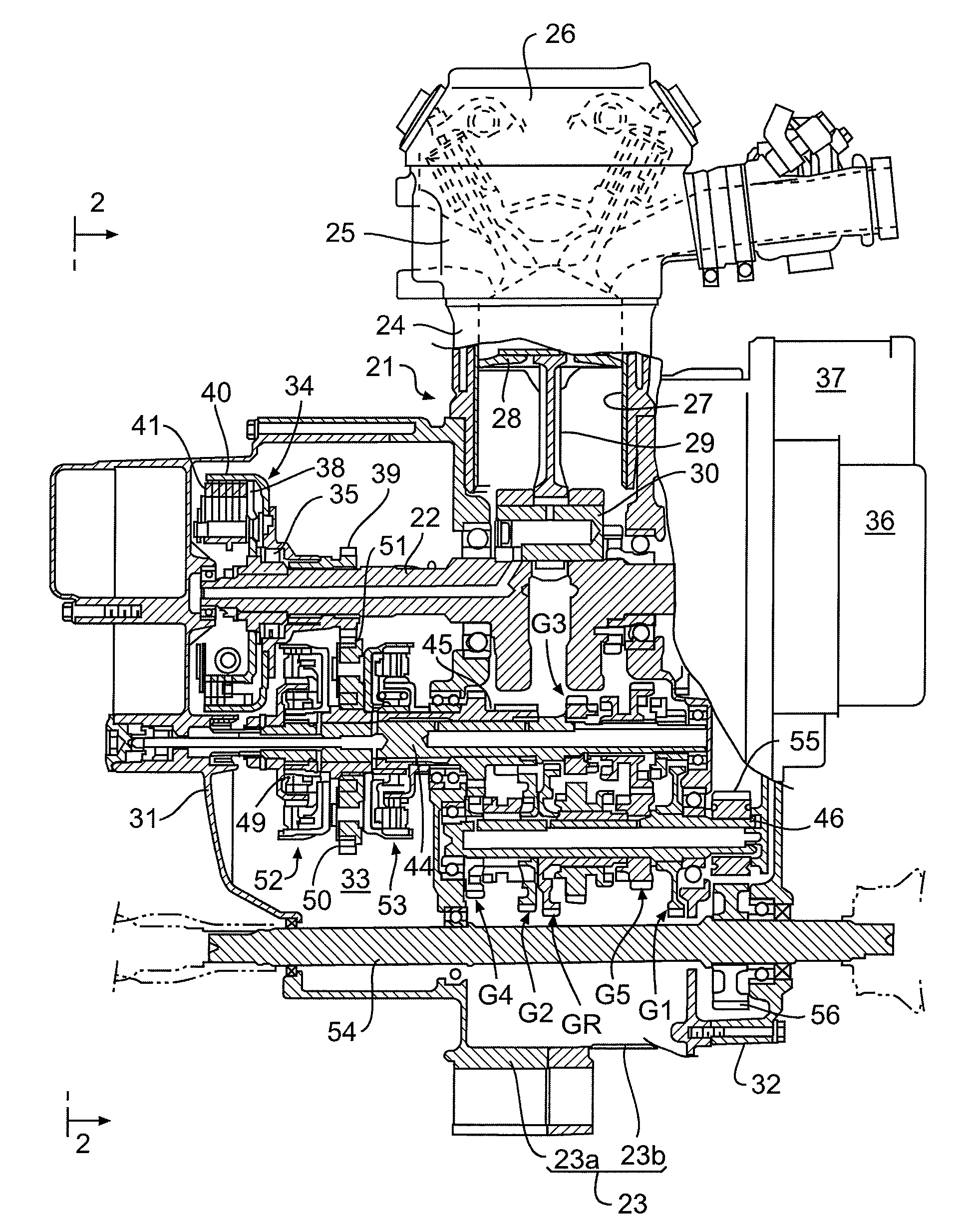
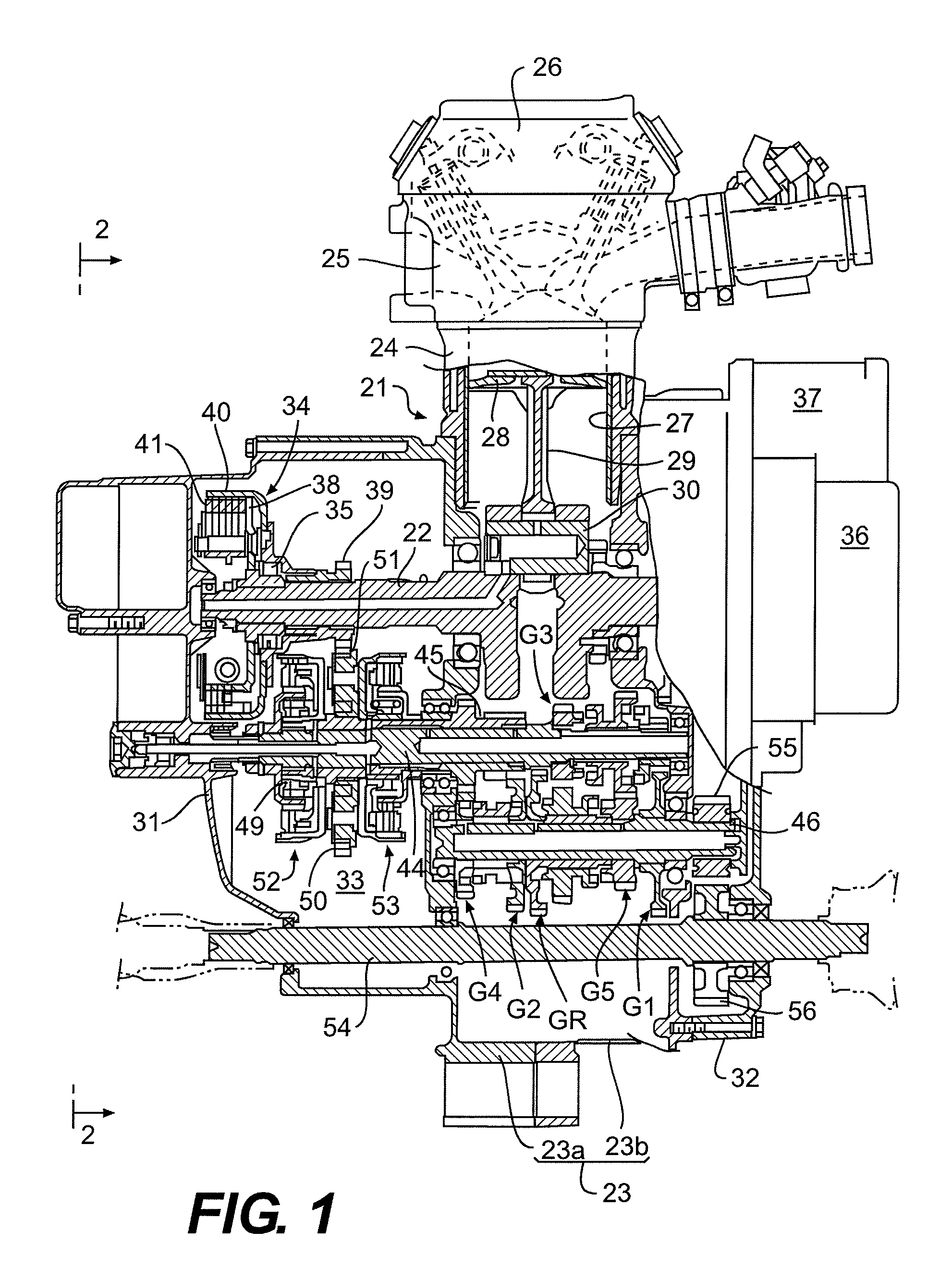
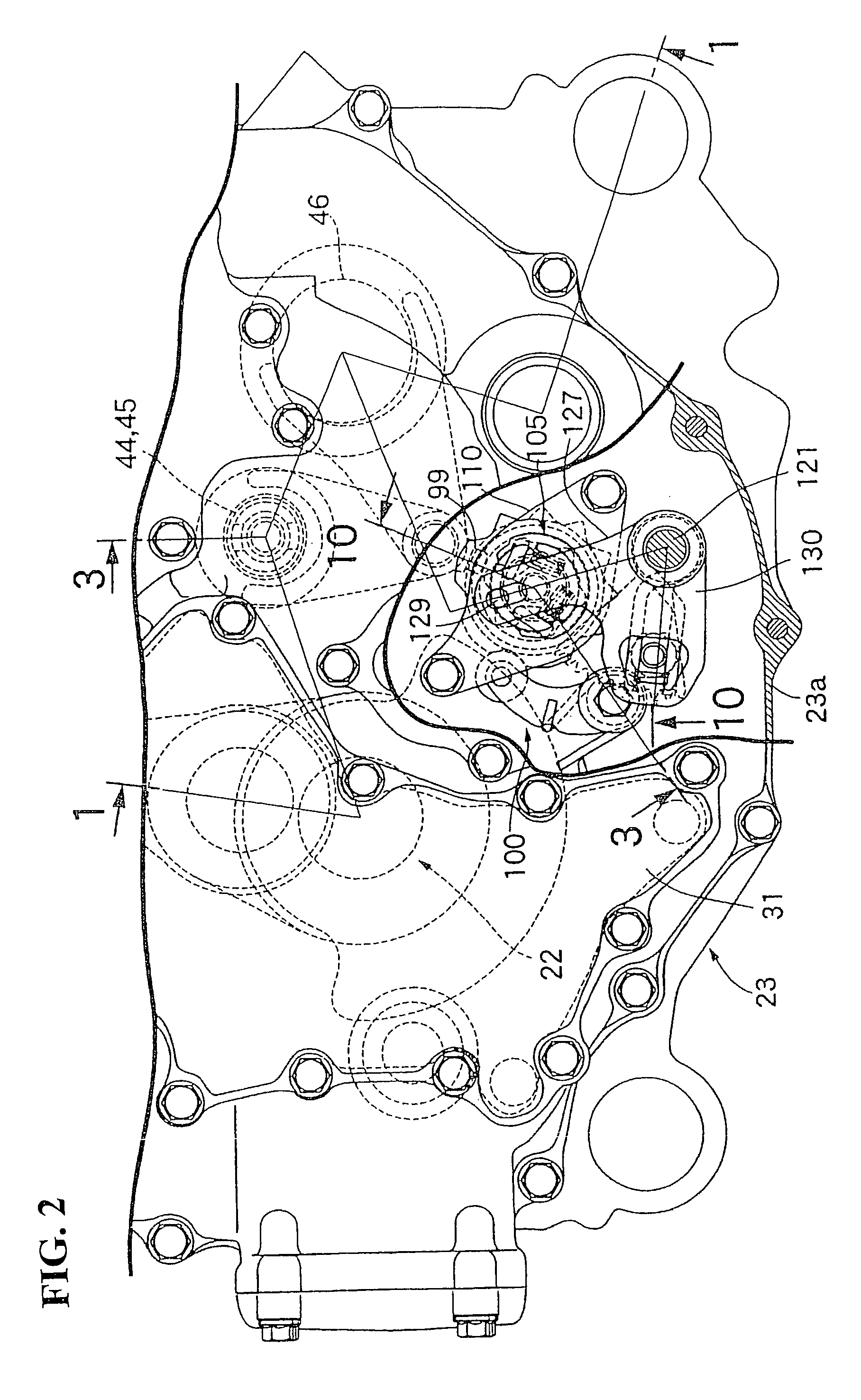
[0051]FIGS. 1 to 19 show a first preferred embodiment of the present invention. Referring first to FIG. 1, an engine E having an engine body 2 is mounted on a vehicle for running in a rough terrain, for example. The engine body 2 includes a crankcase 23 for rotatably supporting a crankshaft 22 having an axis extending in the lateral direction of the vehicle (parallel to the plane of the sheet of FIG. 1), a cylinder block 24 joined to the upper end of the crankcase 23, a cylinder head 25 joined to the upper end of the cylinder block 24, and a head cover 26 joined to the upper end of the cylinder head 25. A piston 28 slidably fitted in a cylinder bore 27 of the cylinder block 24 is connected through a connecting rod 29 and a crankpin 30 to the crankshaft 22.

[0052]The crankcase 23 is composed of a pair of case halves 23a and 23b joined together along a plane perpendicular to the axis of the crankshaft 22. First and second crankcase covers 31 and 32 are fastened to the opposite side sur...


PUM


Abstract

A transmission for a vehicle in which changing a shift position is achieved by sliding a shifter. In sliding the shifter to change the established condition of gear trains respectively corresponding to a plurality of shift positions, the transmission of power from an engine to a main shaft is cut off. A feed mechanism for sliding the shifter is configured to reduce the sliding speed of the shifter in a neutral condition, or to cause the sliding operation of the shifter to have a single stopping action in the neutral condition during the sliding operation of the shifter in changing the established condition of the gear trains. The resulting configuration reduces the engagement noise when changing the shift position.

Description

CROSS-REFERENCE TO RELATED APPLICATION[0001]The present application claims priority under 35 U.S.C. §119 to Japanese Patent Application No. 2006-270043, filed Sep. 29, 2006, the entire contents of which are hereby incorporated by reference.BACKGROUND OF THE INVENTION[0002]1. Field of the Invention[0003]The present invention relates to a transmission for a vehicle including a main shaft to which power from an engine is adapted to be transmitted, a counter shaft connected to a drive wheel, a plurality of gear trains respectively corresponding to a plurality of shift positions and provided between the main shaft and the counter shaft so as to be selectively established, a shifter relatively nonrotatably and slidably supported to the main shaft or the counter shaft to change the established condition of the gear trains, a shift fork for rotatably retaining the shifter, a shift drum having a lead groove on the outer circumference for engaging the shift fork, a shift drum center rotating ...

Claims


Application Information

Patent Timeline
Patent Type & Authority Patents(United States)
IPC IPC(8): F16H59/68F16H3/091F16H61/28F16H63/18
CPCF16H61/32F16H63/18F16H3/006Y10T74/19019Y10T74/19251F16H61/688
Inventor MIZUNO, KINYASAKAGUCHI, KAZUHIKOKITTAKA, EIJIHAMAOKA, SEIJI
Owner HONDA MOTOR CO LTD
Learn More