Partial disk failures and improved storage resiliency

a technology of partial disk and storage resiliency, applied in the field of partial disk failures and improved storage resiliency, can solve the problems of unreliable data storage medium, inability to write or store data, and inability to allow access to data, etc., to reduce the time the spda spends in degraded mode, reduce the extent of adverse performance impact suffered, and reduce the time the spda spends

Active Publication Date: 2011-11-01
NETWORK APPLIANCE INC
View PDF3 Cites 25 Cited by
  • Summary
  • Abstract
  • Description
  • Claims
  • Application Information

AI Technical Summary

Benefits of technology

[0008]This invention relates to allowing a disk to continue to operate even though one of the heads of a multi-head disk is unable to reliably read or write data. A disk which is unable to reliably read or write data through one of its heads but which can read or write data through the other heads is herein referred to as a “partially failed disk.” By allowing a partially failed disk to continue to operate despite a problem associated with one of the heads, some of the data on the disk can be read from the disk and copied to a spare replacement disk. As much data as possible can be copied from the partially failed disk to a spare disk, and any unrecoverable data on the partially failed disk can be rebuilt from the other disks in an SPDA. Since copying data from disk to disk is much faster than rebuilding data in a rebuild process, the time the SPDA spends in degraded mode is reduced. Reducing the time the SPDA spends in degraded mode reduces the chance that a second disk in the SPDA will fail while the SPDA is in degraded mode, thereby reducing the chance that all of the data on the SPDA will become unrecoverable. Reducing the time the SPDA spends in degraded mode also reduces the extent of the adverse performance impact suffered by applications which rely on the SPDA.
[0009]One aspect of the invention relates to a mass data storage system including a disk drive capable of operating as a partially failed disk. The disk drive has a plurality of heads which read and write data from a plurality of rotating magnetic platters. The disk drive also has a disk controller which generally controls the operation of the disk. The disk controller tracks the errors associated with each head and determines when a head is faulty. The disk controller allows continued access to the data on the disk that is accessible.
[0010]Another aspect of the invention relates to a method of reducing the amount of time a striped parity disk array (“SPDA”) in a mass data storage system spends in degraded mode by operating partially failed disks in the SPDA long enough to copy the usable data from the partially failed disk to a spare disk. The method comprises copying recoverable data from a partially failed disk to a spare disk. Unrecoverable data from the partially failed disk is reconstructed through a rebuild process.

Problems solved by technology

Disks eventually suffer enough wear and tear through prolonged use that they become unreliable as a data storage medium.
Typically, when a disk fails it enters a fault mode and ceases to allow access to the data that was written or stored on it.
Restoring data from a backup can be a lengthy process during which services provided by the computer that depend on the data are usually unavailable.
Performance of an SPDA is adversely affected when the SPDA is in degraded mode due to the need to process parity information with available data in order to rebuild the missing data from the failed disk.
Data is usually unrecoverable from a single parity SPDA if a subsequent disk fails while the SPDA is in degraded mode because the SPDA no longer has the redundancy that the parity information provided.
Longer rebuild times have resulted in greater risks or incidences of data loss due to second disk failures while the SPDAs are operating in degraded mode.

Method used


Image

  • Partial disk failures and improved storage resiliency
  • Partial disk failures and improved storage resiliency
  • Partial disk failures and improved storage resiliency

Examples


Embodiment Construction

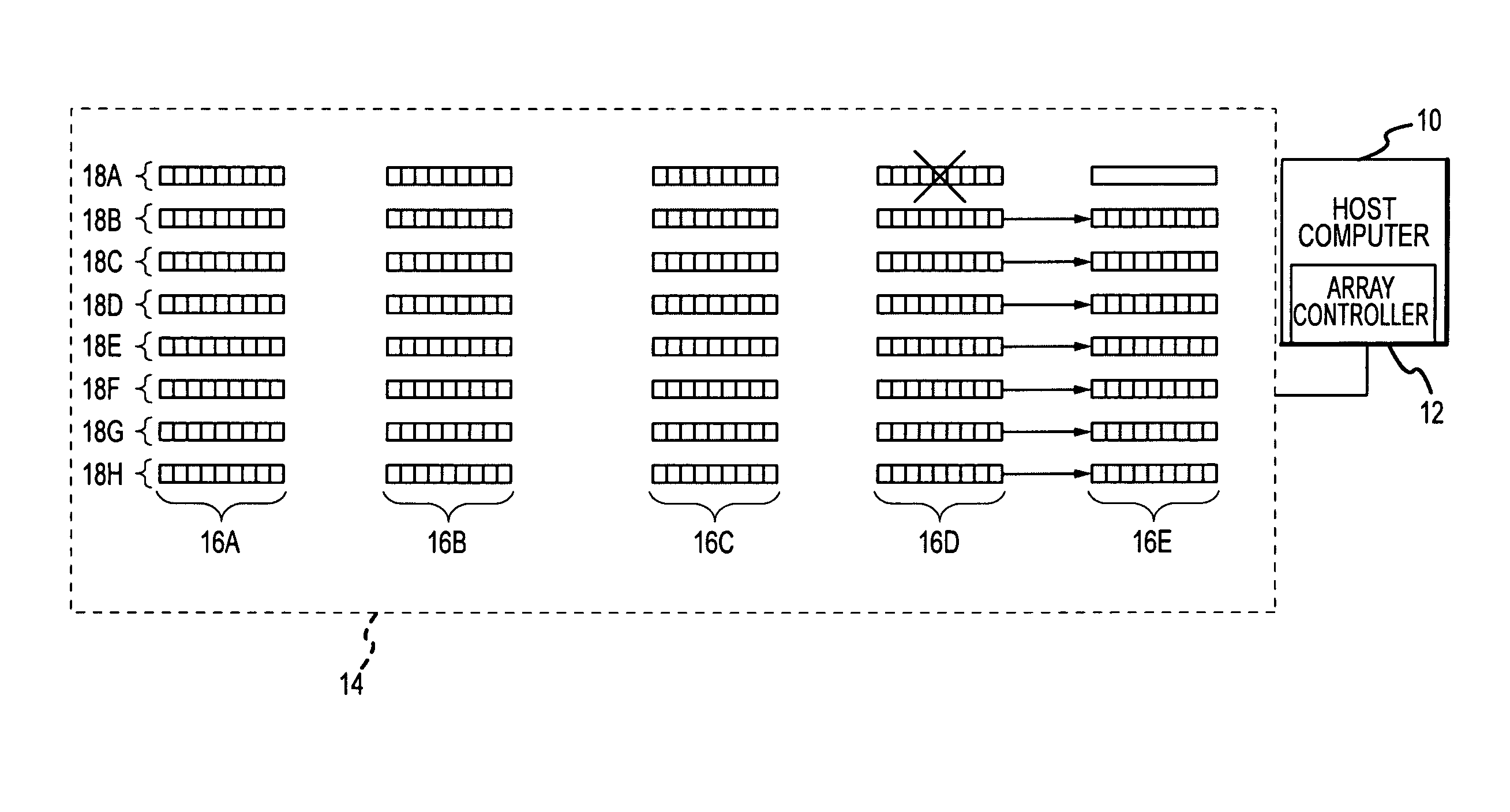
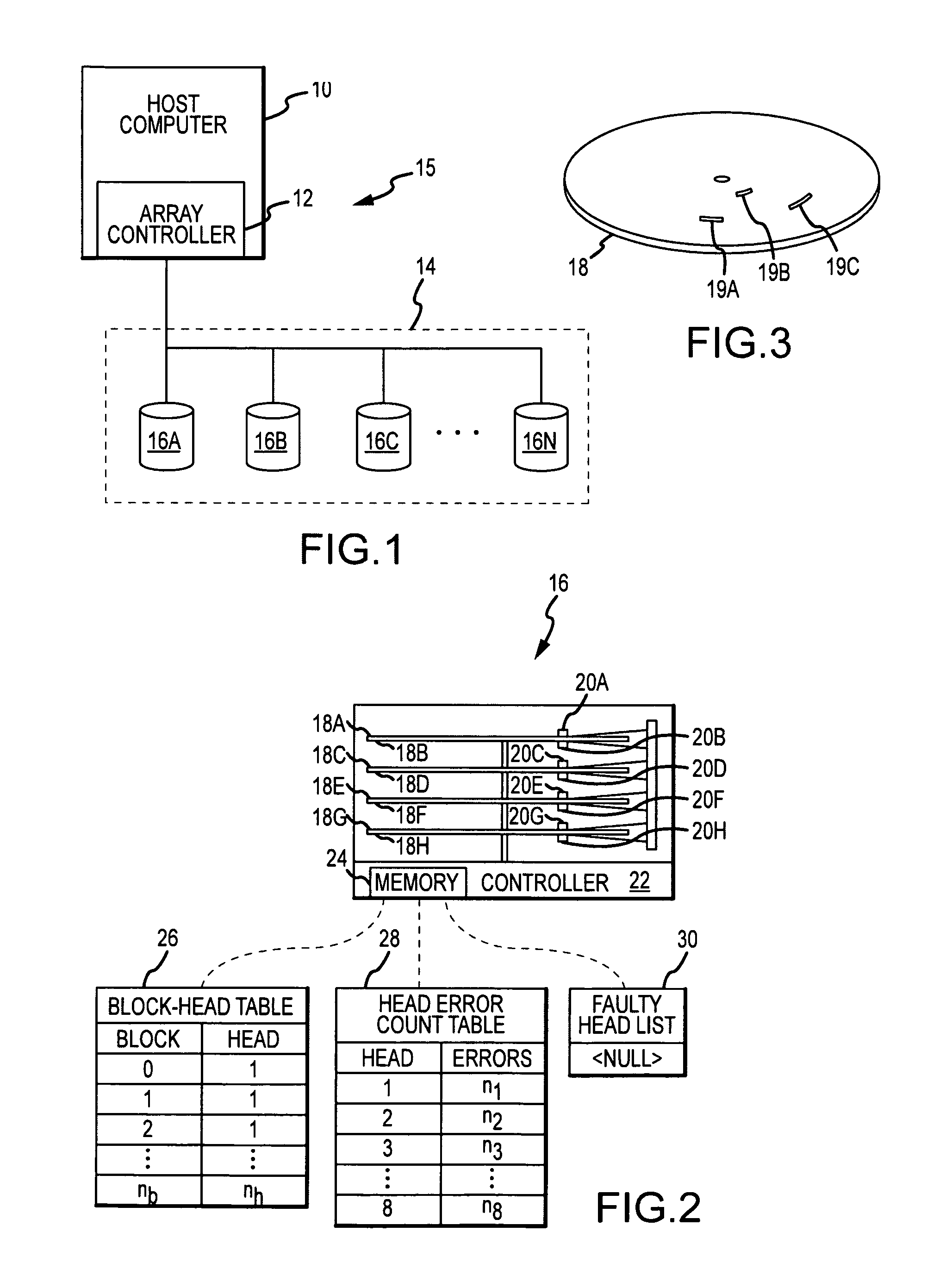
[0019]A host computer 10, array controller 12, striped parity disk array (“SPDA”) 14, and a plurality of disks 16A-16N which implement the present invention and which are collectively referred to as mass data storage system 15 are shown in FIG. 1. The array controller 12 within the host computer 10 manages the SPDA 14 formed by the plurality of disks 16A-16N to which the host computer 10 is connected. The array controller 12 presents the SPDA 14 to the host computer 10 as a single disk, even though the SPDA 14 is composed of several individual disks 16A-16N. The array controller 12 is implemented in software but may alternatively be implemented in hardware of the host computer 10.

[0020]The characteristics of each of the disks 16A-16N is represented by the single disk 16, shown in FIG. 2. The disk 16 comprises several platters, with recording surfaces or platter surfaces 18A-18H, several heads 20A-20H, a disk controller 22, and a memory 24. The heads 20A-20H service the platter surfa...


PUM

PropertyMeasurementUnit
massaaaaaaaaaa
thresholdaaaaaaaaaa
timeaaaaaaaaaa

Abstract

A mass data storage system including a hard disk drive comprising heads and platter surfaces determines when a head of the disk is faulty and the disk continues to operate as a partially failed disk with respect to the remaining heads which are not faulty. A striped parity disk array comprises disks capable of operating as partially failed disks allows copying of data from the platter surfaces not associated with a faulty head of a partially failed disk to a spare disk which reduces the amount of data that must be rebuilt in the rebuild process, thereby reducing the amount of time the array spends in degraded mode exposed to a total loss of data caused by a subsequent disk failure.

Description

[0001]This invention relates to hard disk drives and striped parity disk arrays. More particularly, the invention relates to a new and improved hard disk drive which continues to operate despite having a faulty head to allow data to be retrieved from the non-faulty heads of the hard disk drive and also relates to the improved performance and reduced risk of data loss when such hard disk drives are used in a striped parity disk array.BACKGROUND OF THE INVENTION[0002]Hard disk drives (“disks”) are common data storage devices used in conjunction with computers. Most disks have multiple circular magnetic platters which rotate on a common spindle to allow heads mounted on a common actuator to read and write data from and to both the bottom and top magnetic recording surfaces of each platter. Disks eventually suffer enough wear and tear through prolonged use that they become unreliable as a data storage medium. Typically, when a disk fails it enters a fault mode and ceases to allow access...

Claims


Application Information

Patent Timeline
Patent Type & Authority Patents(United States)
IPC IPC(8): G11B27/36G11B5/09G06F13/00G06F13/28
CPCG11B20/1833G11B27/36G11B2220/2516G11B2220/415
Inventor EMAMI, TIM K.
Owner NETWORK APPLIANCE INC
Why Eureka
Try Eureka