
Automatic injector with needle cover

a technology of automatic injection and needle cover, which is applied in the direction of infusion needles, infusion syringes, other medical devices, etc., can solve the problems of fail-safe operation of the needle cover, and achieve the effect of preventing the rotation of the release pin and simplifying construction

Active Publication Date: 2011-11-01
MYLAN SPECIALTY
View PDF52 Cites 96 Cited by
  • Summary
  • Abstract
  • Description
  • Claims
  • Application Information

AI Technical Summary

Benefits of technology

[0009]One aspect of the present invention relates to an auto-injector for dispensing a predetermined dosage of a medicament. The medicament may be either self administered or administered by a caregiver. The auto-injector includes a housing. The housing is preferably oval or elliptical in shape such that it is more ergonomic. The oval shape prevents the auto-injector from rolling off a table or flat surface, while providing a larger surface area for printing user instructions. A cartridge container is disposed within the housing. A cartridge is received within the cartridge container. The cartridge has at least one opening therein and contains a medicament. The medicament is rearwardly confined by a plunger. The cartridge includes a needle assembly to dispense the medicament therethrough. The cartridge is advanced within the cartridge container from a stored position to an operation position where the needle extends from the cartridge container such that the dose of medicament can be administered. An actuation assembly or power pack provides a stored energy source that is capable of being released to drive the plunger within the cartridge to dispense the medicament through the needle assembly into the user and allowing the needle to be accessible on activation.
[0011]In accordance with another aspect of the present invention, the auto-injector has a first locking assembly that holds the needle cover in the first locked position. The first locking assembly may be located on the cartridge container. The first locking assembly may include at least one locking tooth pivotally connected to the cartridge container or the needle cover. Each locking tooth releasably engages the needle cover and includes a locking surface constructed and arranged to contact a surface on the needle cover or the cartridge container. Each locking tooth may be formed as a separate component that is connected to the container or cover. It is contemplated that the locking teeth may be formed as integral parts of the needle cover or cartridge. A spring force of the locking tooth biases the locking surface into contact with the needle cover. The spring force may be provided by a spring portion of the locking tooth. The spring force may also be provided by a separate spring assembly biasing the locking surface into contact with the needle cover. Each locking tooth is preferably pivotally connected to the cartridge container. Each locking tooth pivots in response to movement of the cartridge within the cartridge container. It is also contemplated that the locking teeth can pivot in response to movement of the collet or the power pack. Typically, the locking surface pivots out of contact with the needle cover when the locking tooth pivots in response to the movement of the cartridge. The spring force and the force exerted by the locking teeth on the cartridge are controlled such that they negligibly or minimally impede the motion of the cartridge during the injection operation to avoid any premature rupturing of the diaphragm within the cartridge and premature administering of the medicament.
[0012]The needle cover is spring biased so that the cover is biased outwardly from the housing to cover the exposed needle after the first locking assembly is released. In accordance with another aspect of the present invention, the auto-injector has a second locking assembly that holds the needle cover in the second locked position. The second locking assembly may be located on the cartridge container, the outer body or the cover member. The second locking assembly may include at least one locking arm or wing preferably connected to the cartridge container. Each locking arm is spaced from the cartridge container such that the locking arm can be temporarily compressed against the cartridge container as the needle cover moves from the first locked position to the second locked position. Each locking arm has a locking surface to engage the needle cover when the needle cover is in the locked extended position. Each locking arm has a thick strut portion and a thin strut portion, wherein the thick strut portion is outwardly curved and the thin strut portion is inwardly curved. This construction maintains the locking arm in a normal uncompressed state to reduce stress on the cartridge container. This also permits a smooth deployment of the cover member. Furthermore, this arrangement ensures that the thick strut portion will buckle into a stable condition. This creates a stronger lock to prevent the cover member from being moved rearwardly to a retracted position. The inwardly curved nature of the thin strut portion allows the thick portion to buckle in a controlled manner to a stable condition. Additionally, the outwardly curved shape of the thick strut portion provides for fail safe locking of the cover member in the extended position. In the event that the thin strut breaks, the thick strut portion will still engage the cover member to maintain it in an extended locked position.
[0014]Another aspect of the present invention is the construction and arrangement of the actuation assembly or power pack, which is mounted within the housing adjacent to an open end. A release pin or safe pin is removably attached to the actuation assembly to prevent inadvertent actuation of the auto-injector when the release pin is in place. A pin or stem on the release pin is received within an opening in the actuation assembly to prevent actuation of the auto-injector. This opening in the power pack is spaced from the open end of the housing such that the opening is less visible to a user prior to administering the drug. This arrangement is provided so that user will not orient the incorrect end of the auto-injector against the injection surface of the user. The power pack is recessed or spaced from the end of the housing, which provides an indication to the user that pressing the power pack will not operate the auto-injector. The recessed nature of the power pack serves to hide the release pin hole in the power pack when the user is viewing the instructions on the outer body such that the user does not confuse the release pin hole with the opening through which the needle passes for administering the medicament. The release pin includes at least one tab extending therefrom. The tab is compression fit into a complimentary recess formed in the actuation assembly to prevent the inadvertent removal of the release pin. The tabs also prevent rotation of the release pin such that the user easily recognizes that the release pin must be pulled in order to be removed.
[0015]The actuation assembly includes an outer body, which is configured to engage the release pin. The outer body is constructed to be connected to the housing. An inner body is operatively coupled to the outer body. At least one retention tab on the inner body secures the inner body to the outer body. The inner body is capable of limited movement with respect to the outer body. A collet is operatively coupled to the inner body. An energy source is operatively connected to the inner body and the collet. Unlike conventional collets, the collet in the present invention is molded as a single piece. No spacers or other components are provided between the collet and the plunger in the cartridge. This arrangement simplifies construction. Different sized collets can be produced and installed into the actuation assembly, such that only the collet needs to altered when different sized cartridges are used or a different sized dosage of medicament is to be administered.

Problems solved by technology

Theoretically, the operation of the needle cover is fail safe because the cover will not deploy until after the needle penetrates the user.

Method used


Image

  • Automatic injector with needle cover
  • Automatic injector with needle cover
  • Automatic injector with needle cover

Examples


Embodiment Construction

[0078]It should be appreciated that some of the components described herein are conventionally known in the broader aspects, as described in U.S. Pat. No. 4,031,893 (“the '893 patent”) hereby incorporated by reference in its entirety, and thus not described in unnecessary detail here. It should also be appreciated that known modifications or variations to the '893 patent can apply equally to the auto-injector of the present invention as will be described below. These modifications or variations include embodiments described in U.S. Pat. Nos. 4,226,235; 4,329,988; 4,394,863; 4,723,937; and U.S. Ser. Nos. 09 / 985,466; 10 / 285,692, each of which is incorporated by reference in its entirety for the full teachings therein.

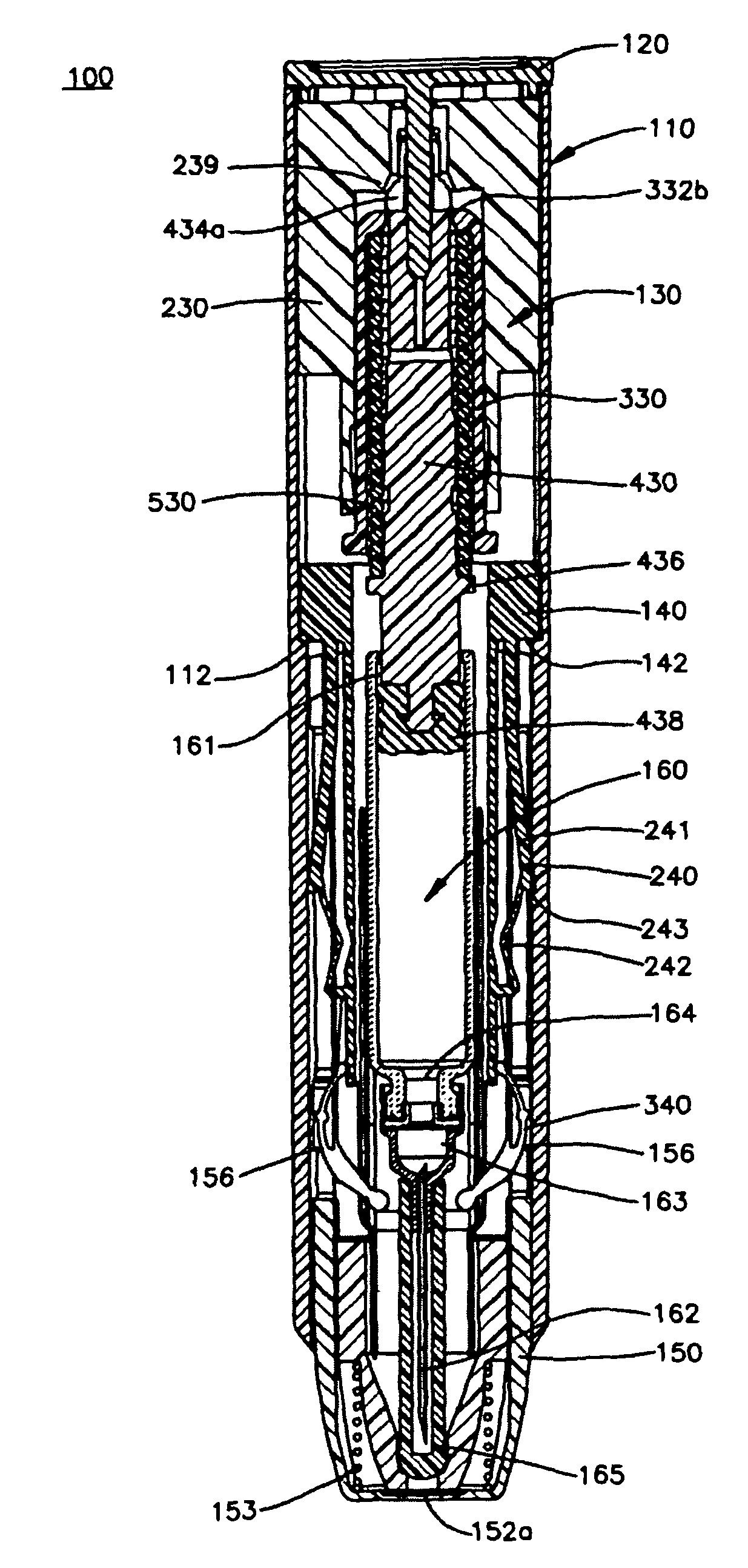
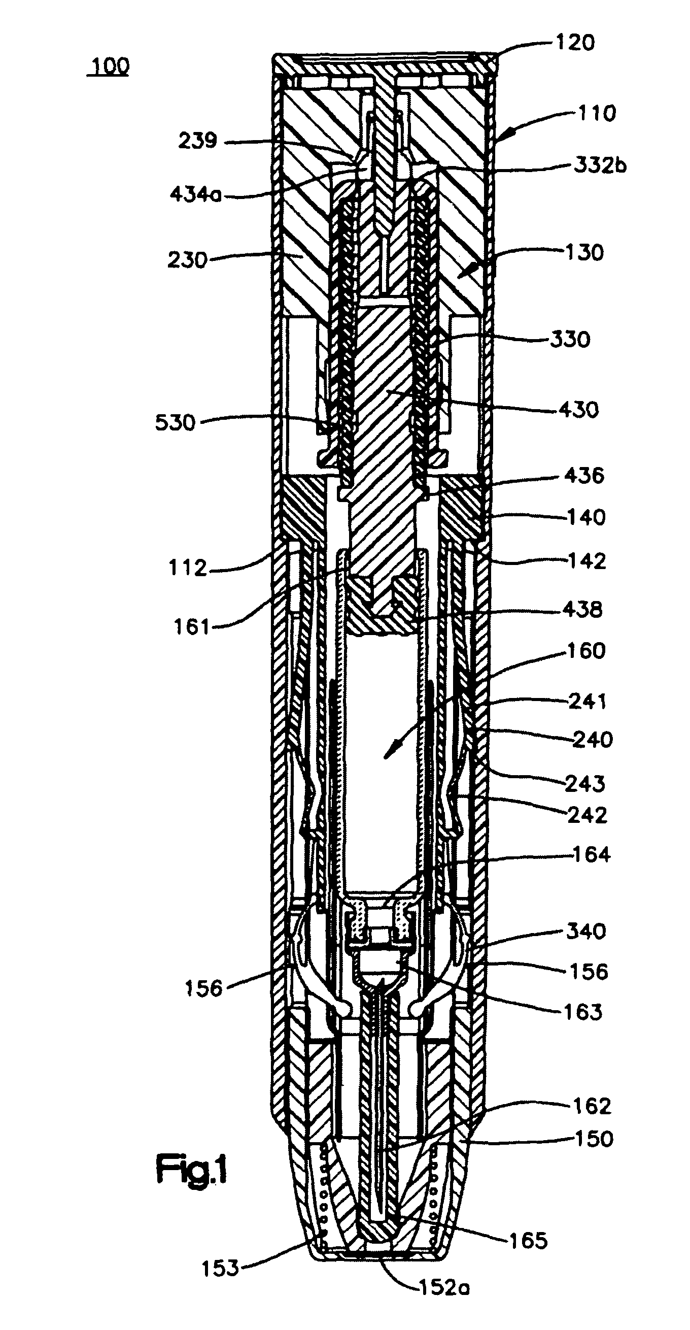
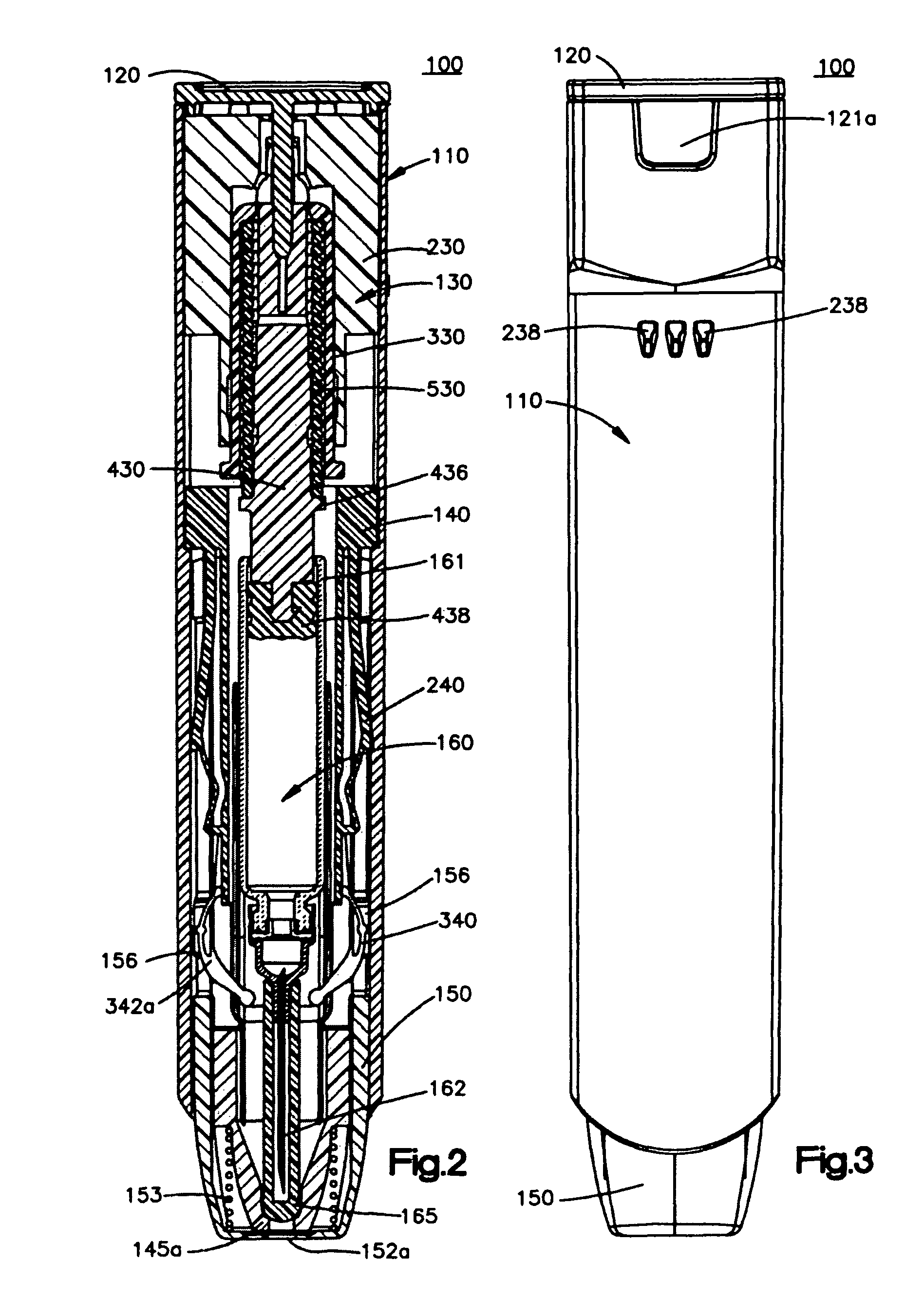
[0079]An auto-injector 100 of the present invention will now be described in greater detail in connection with FIGS. 1-59. The auto-injector 100 includes an outer body 110, a release pin 120, a power pack 130, a cartridge container 140, a needle cover 150 and a cartridge ...


PUM


Abstract

An auto-injector automatically dispenses a predetermined dose of medicament upon activation. The auto-injector includes a needle cover operative to engage an injection site and activate the injector. The needle cover is configured to move from a locked retracted position prior to a medicament dispensing operation to a locked extended position after the medicament dispensing operation. The non-removable needle cover prevents contact with the needle both before and after the medicament dispensing operation.

Description

CROSS-REFERENCE TO RELATED APPLICATIONS[0001]This is a continuation-in-part of U.S. patent application Ser. No. 11 / 095,664, filed Apr. 1, 2005, now U.S. Pat. No. 7,449,012, which claims the benefit of U.S. Provisional Application No. 60 / 599,054, filed Aug. 6, 2004, the entire contents of each are expressly incorporated herein by reference thereto.FIELD OF THE INVENTION[0002]The invention relates to an automatic injector or auto-injector for delivering medicament to an injection site. In particular, the invention is directed to an auto-injector having a needle cover mechanism to prevent a user from coming into contact with the needle of the auto-injector after use. The needle cover mechanism is held in a locked position prior to activation of the auto-injector. After injection, the needle cover mechanism is held in a locked deployed position such that the user cannot access the needle.[0003]The invention is also directed to an auto-injector having a power pack containing a one-piece ...

Claims


Application Information

Patent Timeline
Patent Type & Authority Patents(United States)
IPC IPC(8): A61M5/32
CPCA61M5/2033A61M5/5086A61M5/3202A61M5/3245A61M5/24A61M5/3129A61M5/326A61M5/3271A61M2005/2013A61M2005/206A61M2005/2073A61M2005/3118A61M2005/3247A61M2205/583A61M5/2459A61M5/31578A61M2005/2403A61M2005/3125
Inventor MESA, C. MICHAELCORS, SARAH JANEPENNEY, MELINDA FISCHERTOMELLINI, DALITA ROSEMARIEBREMLEY, MARK BUMBWILMOT, JOHN GLYNDWRYOUNG, MATTHEW EGERTONRAVEN, SOPHIE REBECCAMURPHY, MARTIN JOSEPHHURLSTONE, CHRISTOPHER JOHNDAINTREY, JOSEPH WILLIAMROCHFORD, CRAIG MALCOLMKIRKWOOD, STEPHEN PHILIPMATHEWS, COLIN JAMESHILL, ROBERT L.
Owner MYLAN SPECIALTY
Learn More