
Acoustic treatment device for turbine and combustion noises

a technology for turbines and treatment devices, which is applied in the direction of machines/engines, air-flow influencers, transportation and packaging, etc., can solve the problems of difficult to adapt the shape of the honeycomb structure to the high curvature of the outside face of the plug, the available space in the plug cannot allow thicker treatments to attenuate lower frequency noise, and the plug is not suitable for a wide range of noise reduction

Active Publication Date: 2011-10-18
AIRBUS OPERATIONS (SAS)
View PDF15 Cites 20 Cited by
  • Summary
  • Abstract
  • Description
  • Claims
  • Application Information

AI Technical Summary

Benefits of technology

The invention is an acoustic treatment device for the internal structure of a primary ejection duct from turbojet engines. The device aims to reduce noise in the duct by using a honeycomb structure and a micro-porosity separating wall. The device can attenuate high frequency turbine noise and low frequency combustion noise. The honeycomb structure is made of thin layers and an acoustic reflector to enhance attenuation of low frequency acoustic waves. The device can be easily integrated into the plug and can be combined with other treatments such as thin layers for increased attenuation of high frequency noise.

Problems solved by technology

However, the available space in the plug does not allow thicker treatments to attenuate lower frequency noise.
However, it is then difficult to integrate several honeycomb layers on the outside surface of the plug, due to the necessary size of such an assembly.
Furthermore, it is also difficult to adapt the shape of the honeycomb structure to the high curvature of the outside face of the plug while maintaining good acoustic efficiency.
This device that processes low frequencies, for example frequencies of the order of 400 Hz, does not handle high frequencies.

Method used


Image

  • Acoustic treatment device for turbine and combustion noises
  • Acoustic treatment device for turbine and combustion noises

Examples


Embodiment Construction

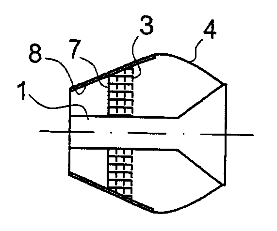
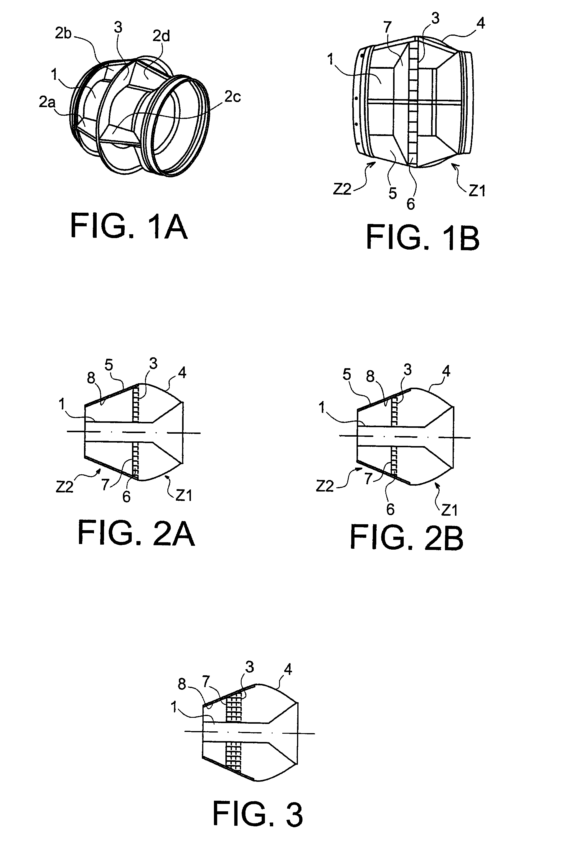
[0021]FIGS. 1A and 1B show a perspective view and a sectional view respectively of an internal structure of a primary ejection duct fitted with a noise treatment device according to the invention.

[0022]The internal structure of the primary ejection duct (plug) is a structure known in itself that will be briefly described below. FIG. 1A shows a perspective view of the structure without its outside walls and FIG. 1B shows a longitudinal sectional view of the structure with its outside walls.

[0023]The structure comprises a central body 1 that opens up in the form of funnel at one of its ends, a transverse separating wall 3 and longitudinal separating walls 2a, 2b, 2c, 2d, etc. on each side of the transverse separating wall 3. The transverse separating wall 3 separates the plug into an upstream zone Z1 and a downstream zone Z2, defined relative to the direction of the airflow circulating in the ejection circuit. The upstream zone is located on the funnel side of the central body 1 and t...


PUM


Abstract

An acoustic treatment device for an internal primary ejection duct from a turbojet pod, including an upstream zone and a downstream zone relative to an airflow direction in the primary ejection duct, the upstream and downstream zones being located on each side of a separating wall with a first face on the side of the upstream side and a second face on the side of the downstream side. The separating wall is a micro-porous wall and the face of the separating wall located on the side of the downstream side is covered by a honeycomb structure to attenuate high frequency acoustic waves. Such a device may find application to treatment of combustion and turbine noises.

Description

TECHNICAL FIELD OF THE INVENTION AND PRIOR ART[0001]The invention relates to an acoustic treatment device for turbine noise, and more particularly an acoustic treatment device for the internal structure of the primary ejection duct from turbojet pods, more commonly referred to as “plugs”.[0002]Two noise sources are predominant in the primary ejection ducts; high frequency turbine noise (frequencies of the order of 5000 Hz) and low frequency combustion noise (frequencies between 300 Hz and 1000 Hz).[0003]Different types of acoustic treatment are known to attenuate noise that propagates in primary ejection ducts. A first type consists of placing thin cellular layers on the outside face of the plug to attenuate high frequency noise (turbine noise). Thicker layers (for example that may be about fifteen centimetres thick) have also been envisaged. These layers can then be used to attenuate frequencies of the order of 800 Hz. However, the available space in the plug does not allow thicker...

Claims


Application Information

Patent Timeline
Patent Type & Authority Patents(United States)
IPC IPC(8): E04B1/82
CPCF02K1/827F05D2260/96F05D2250/283
Inventor MERCAT, FLORENT
Owner AIRBUS OPERATIONS (SAS)
Learn More