
Passive noise attenuation system

a passive noise and attenuation technology, applied in the field of noise attenuation, can solve the problems of dissipation of noise and/or instability generated upstream, and achieve the effects of reducing noise and/or instability

Active Publication Date: 2010-03-11
UNIVERSITY OF ALABAMA
View PDF23 Cites 11 Cited by
  • Summary
  • Abstract
  • Description
  • Claims
  • Application Information

AI Technical Summary

Benefits of technology

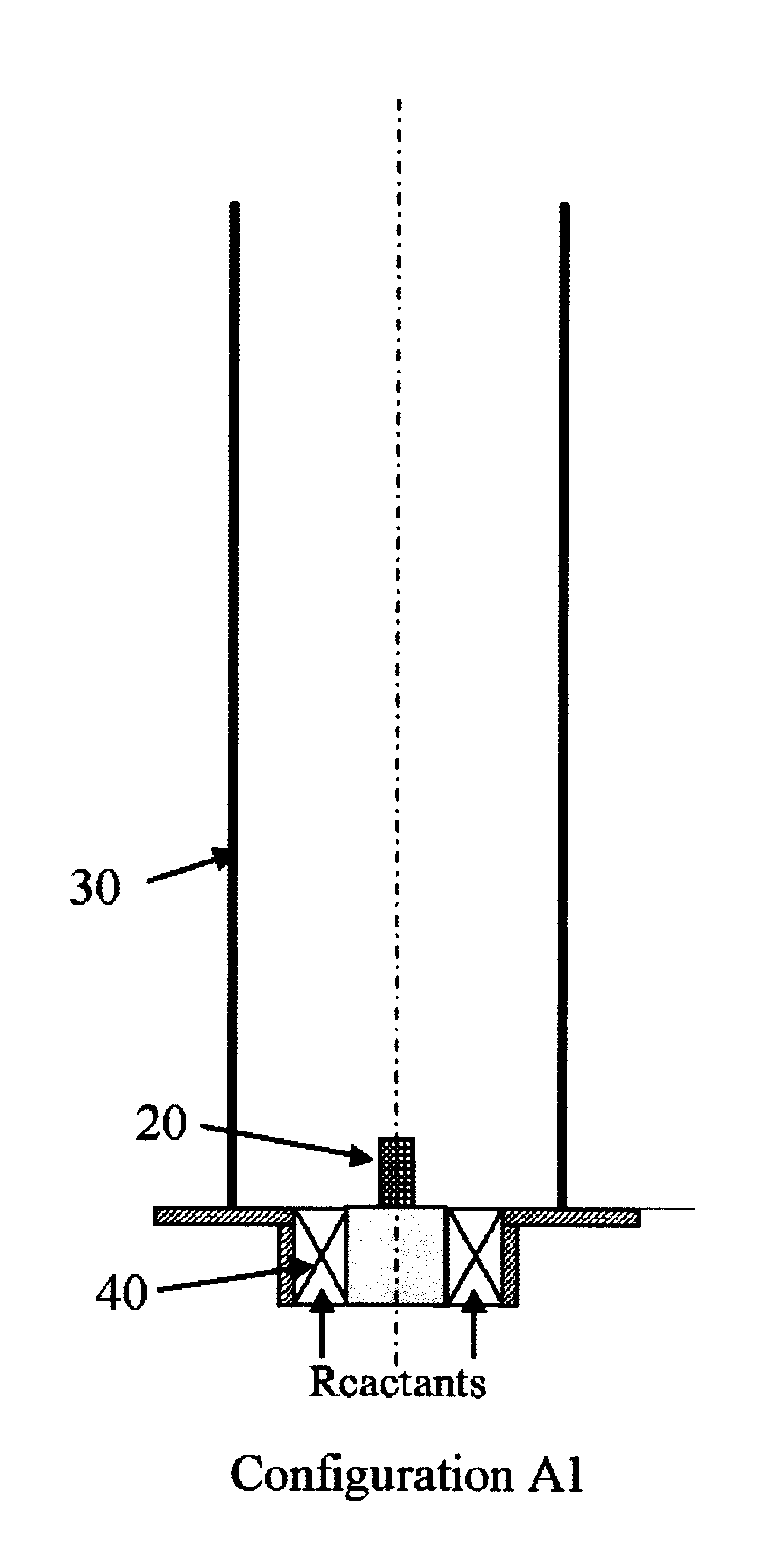
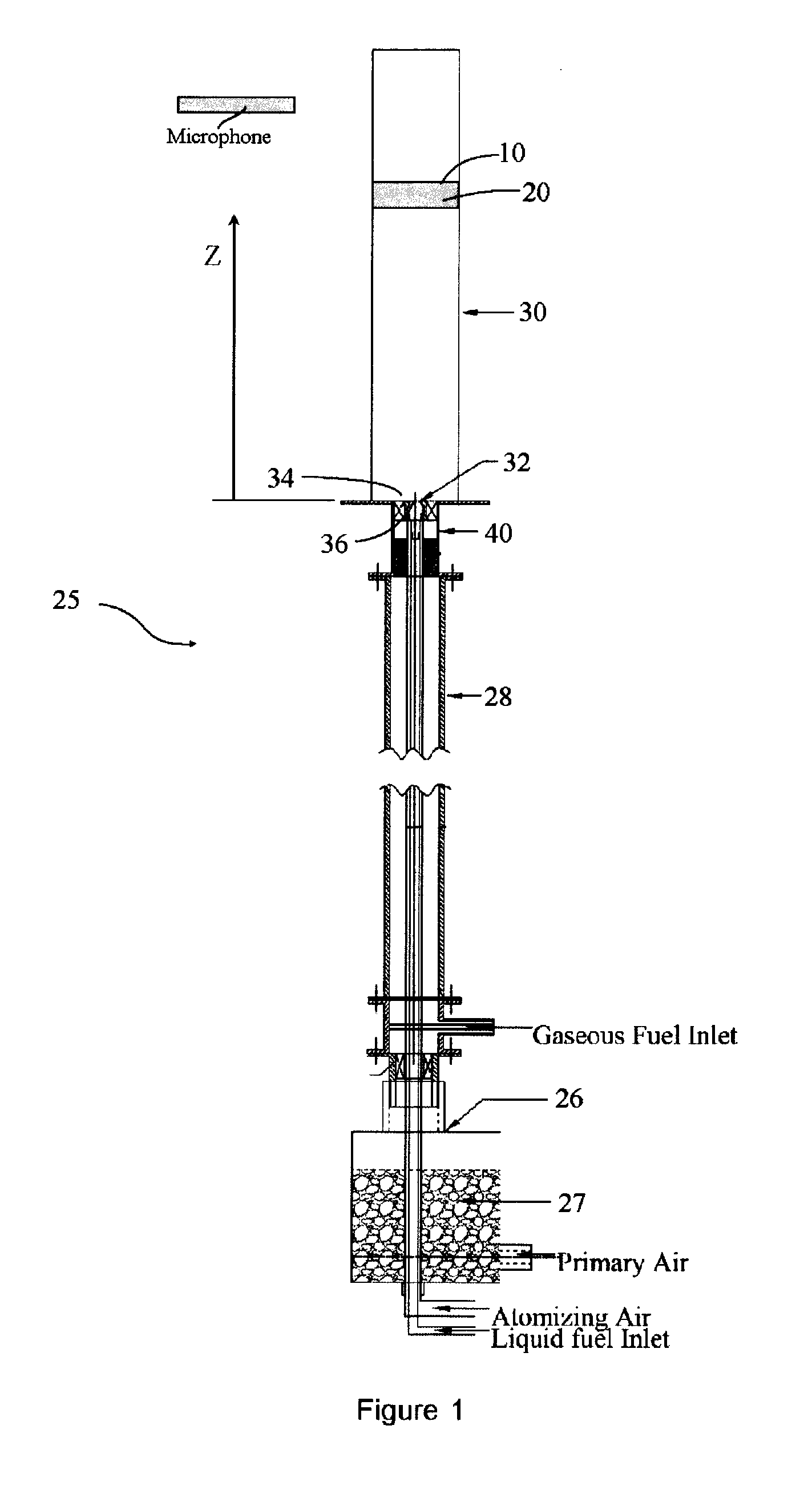
[0006]In one aspect, the passive noise attenuation device can have a reticulated open-cell porous structure configured to act as a passive control device to mitigate combustion noise and instability problems in turbine engines. In this aspect, the porous structure can be placed downstream of a reaction zone of the combustion system and can dissipate noise and / or instability generated upstream in the flame. In another aspect, the porous structure can be placed in the reaction zone of the combustion system. In this aspect, the vortex shedding mechanism of combustion noise and / or instability can be curtailed on source by inserting the porous structure in the reaction zone to constrain recirculation and / or high turbulence intensity regions. In a further aspect, the porous structure can limit and / or disintegrate vortical structures in the flame to produce a homogeneous flow field to facilitate distributed reaction zones. Optionally, combustion sustained within the porous insert can also provide the ignition energy needed to stabilize the flame.

Problems solved by technology

In spite of the significant progress in these areas, complete reliability of active combustion control in turbine engines is still a major concern, since an unexpected event can destroy the engine within a fraction of a second.
In this aspect, the porous structure can be placed downstream of a reaction zone of the combustion system and can dissipate noise and / or instability generated upstream in the flame.

Method used


Image

  • Passive noise attenuation system
  • Passive noise attenuation system
  • Passive noise attenuation system

Examples


Embodiment Construction

[0021]The present invention can be understood more readily by reference to the following detailed description, examples, drawing, and claims, and their previous and following description. However, before the present devices, systems, and / or methods are disclosed and described, it is to be understood that this invention is not limited to the specific devices, systems, and / or methods disclosed unless otherwise specified, as such can, of course, vary. It is also to be understood that the terminology used herein is for the purpose of describing particular aspects only and is not intended to be limiting.

[0022]The following description of the invention is provided as an enabling teaching of the invention in its best, currently known embodiment. To this end, those skilled in the relevant art will recognize and appreciate that many changes can be made to the various aspects of the invention described herein, while still obtaining the beneficial results of the present invention. It will also...


PUM


Abstract

A passive noise attenuation device and system is provided having a reticulated open-cell porous structure configured to acts as a passive control device in order to mitigate combustion noise and instability problems in combustion systems. A porous inert media structure is placed downstream of the reaction zone of a combustion chamber to dissipate noise and / or instability generated upstream in the flame. The porous inert media also limits and / or disintegrates vortical structures in the flame to produce a homogeneous flow field to facilitate distributed reaction zones.

Description

[0001]This application claims priority to and the benefit of U.S. Provisional Application No. 61 / 054,359, filed on May 19, 2008, and U.S. Provisional Application No. 61 / 058,812 filed on Jun. 4, 2008, both of which are incorporated in their entirety in this document by reference.FIELD OF THE INVENTION[0002]The field of this invention relates generally to noise attenuation and more particularly to passive noise attenuation at the source in combustion systems.BACKGROUND OF THE INVENTION[0003]In recent years, significant efforts to suppress combustion noise and instabilities have been reported in the context of lean premixed gas turbine combustion systems. The effectiveness of an active combustion control system depends upon actuation, sensing, and control algorithms, among other factors. In spite of the significant progress in these areas, complete reliability of active combustion control in turbine engines is still a major concern, since an unexpected event can destroy the engine with...

Claims


Application Information

Patent Timeline
IPC IPC(8): F01N1/24
CPCF23M20/005F23R2900/00014
Inventor AGRAWAL, AJAY K.SADASIVUNI, VIJAYKANT
Owner UNIVERSITY OF ALABAMA
Learn More