Control system for compression-ignition engine

a control system and compression ignition technology, applied in electrical control, ignition automatic control, non-mechanical valves, etc., can solve the problems of excessive combustion noise, and excessive rise in in-cylinder temperature near the tdc of compression stroke, so as to reduce the ratio of in-cylinder temperature and improve thermal efficiency.

Active Publication Date: 2020-09-08
MAZDA MOTOR CORP
View PDF15 Cites 8 Cited by
  • Summary
  • Abstract
  • Description
  • Claims
  • Application Information

AI Technical Summary

Benefits of technology

[0008]The present disclosure is made in view of the above situations and aims to provide a control system for a compression-ignition engine, which reduces combustion noise while achieving suitable flame propagation of SI combustion in SPCCI combustion.

Problems solved by technology

As a result, it was found that in a condition where the engine load is relatively high and the in-cylinder temperature easily rises, advancing the open timing of the intake valve increases the residual gas (burnt gas remaining inside the cylinder) amount, which raises the in-cylinder temperature when the compression stroke starts due to the heat of the residual gas, and the in-cylinder temperature near TDC of compression stroke excessively rises.
Thus, the pressure increase caused by the heat generation of the CI combustion becomes excessive and results in generating excessive combustion noise.

Method used


Image

  • Control system for compression-ignition engine
  • Control system for compression-ignition engine
  • Control system for compression-ignition engine

Examples


Embodiment Construction

(1) Overall Configuration of Engine

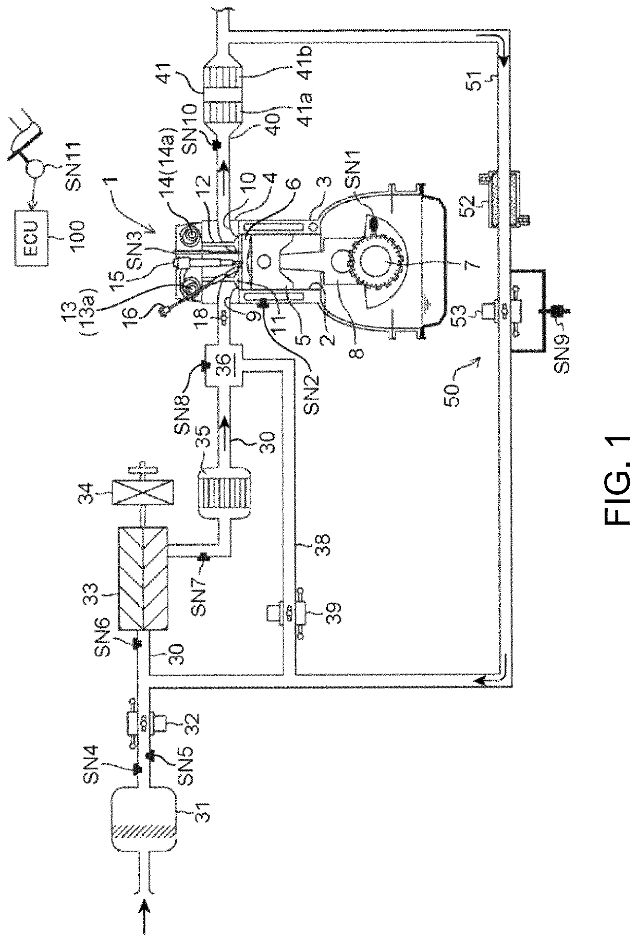
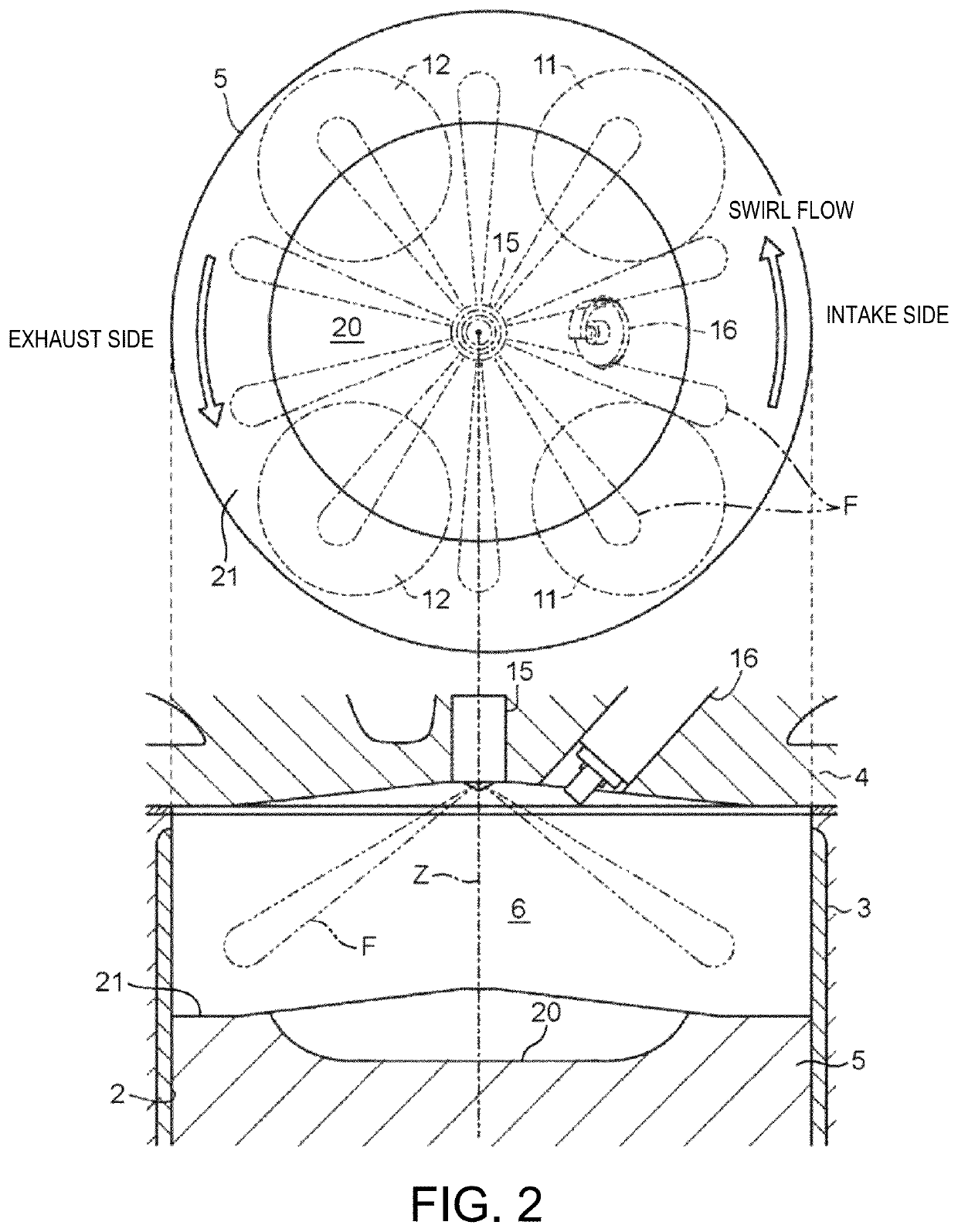
[0055]FIGS. 1 and 2 are diagrams illustrating a suitable embodiment of a compression-ignition engine (hereinafter, simply referred to as “the engine”) to which a control system of the present disclosure is applied. The engine illustrated in FIGS. 1 and 2 is a four-cycle gasoline direct-injection engine mounted on a vehicle as a drive source for traveling, and includes an engine body 1, an intake passage 30 through which intake air to be introduced into the engine body 1 flows, an exhaust passage 40 through which exhaust gas discharged from the engine body 1 flows, and an external exhaust gas recirculation (EGR) device 50 which recirculates a portion of the exhaust gas flowing through the exhaust passage 40 to the intake passage 30. This external EGR device 50 is one example of an “EGR device.”

[0056]The engine body 1 has a cylinder block 3 formed therein with cylinders 2, a cylinder head 4 attached to an upper surface of the cylinder block 3 so as t...


PUM


Abstract

A compression-ignition engine control system is provided, which includes an intake variable mechanism and a controller. Within a first operating range and a second operating range on a higher engine load side, the controller controls the variable mechanism to form a gas-fuel ratio (G / F) lean environment in which an air-fuel ratio inside a cylinder is near a stoichiometric air-fuel ratio and burnt gas remains inside the cylinder, and controls a spark plug to spark-ignite mixture gas inside the cylinder to combust in a partial compression-ignition combustion. The controller controls the variable mechanism to advance the intake valve open timing on an advancing side of a TDC of the exhaust stroke, as the engine load increases within the first range, and retard the intake valve open timing on the advancing side of the TDC of the exhaust stroke, as the engine load increases within the second range.

Description

TECHNICAL FIELD[0001]The present disclosure relates to a control system for a compression-ignition engine, which executes partial compression-ignition combustion in which a mixture gas within a cylinder is partially combusted by spark-ignition (SI combustion) and then the remaining mixture gas is combusted by self-ignition (CI combustion).BACKGROUND OF THE DISCLOSURE[0002]Recently, Homogeneous-Charge Compression Ignition (HCCI) combustion in which a gasoline fuel mixed with air is combusted by self-ignition inside a sufficiently compressed combustion chamber has attracted attention. HCCI combustion is a mode in which the mixture gas combusts at a plurality of positions simultaneously without flame propagation, and thus has a higher combustion speed of the mixture gas than in SI combustion (spark-ignition combustion) which is adopted for general gasoline engines. Therefore, HCCI combustion is said to be significantly advantageous in terms of thermal efficiency. However, in a case of ...

Claims


Application Information

Patent Timeline
Patent Type & Authority Patents(United States)
IPC IPC(8): F02D41/30F02D13/02F02D41/00F01L9/04
CPCF02D41/3041F02D13/0215F01L2009/0492F02D2041/001F02D37/02F02D41/0002F02D41/0007F02D13/0261F02D2200/101F02D41/0057F02D41/006F02D2200/1002F02P5/1502F02B23/101F02D2041/0015F02B2023/108F02P5/045Y02T10/12Y02T10/40F01L2009/4092
Inventor INOUE, ATSUSHISUEOKA, MASANARIMARUYAMA, KEIJIOHURA, TAKUYANISHIDA, TOMOHIROKAWAI, YUSUKECHIKADA, TETSUYATOKUNAGA, TATSUHIRO
Owner MAZDA MOTOR CORP
Why Eureka
Try Eureka