
Compression ignition gasoline engine

a gasoline engine and compression ignition technology, applied in the direction of machines/engines, output power, electric control, etc., can solve the problems of engine durability problems, unburned fuel generation soot, and the rate of the engine significantly increases the noise level that a driver feels, so as to reduce the noise of combustion, and reduce the effect of self-inflammation

Active Publication Date: 2013-11-26
HYUNDAI MOTOR CO LTD
View PDF3 Cites 8 Cited by
  • Summary
  • Abstract
  • Description
  • Claims
  • Application Information

AI Technical Summary

Benefits of technology

The solution effectively reduces combustion noise, stabilizes combustion, prevents coking, and improves fuel efficiency and emission by managing combustion pressure ascension rates and using multiple ignition to suppress excessive self-ignition.

Problems solved by technology

The increase of the rate significantly increases the noise level that a driver feels and causes a problem in engine durability.
However, since the solenoid-type injector is small in injection rate, 14-15 g / sec, the number of multiple injection is limited when it is required to inject the fuel several times for a short time, and particularly, it may cause a problem, such as coaking.
In this case, unburned fuel generates soot and the injection hole of the injector is clogged with the soot.
The coking makes wrong changes in the injection amount and shape of the injector, and as a result, the combustion becomes unstable and the engine fails.
Therefore, it is impossible to perform compression process injection that generates combustion by a limit in selection of injection time due to the problem and it is also difficult to perform multiple injection above two times.

Method used


Image

  • Compression ignition gasoline engine
  • Compression ignition gasoline engine
  • Compression ignition gasoline engine

Examples


Embodiment Construction

[0044]Reference will now be made in detail to various embodiments of the present invention(s), examples of which are illustrated in the accompanying drawings and described below. While the invention(s) will be described in conjunction with exemplary embodiments, it will be understood that present description is not intended to limit the invention(s) to those exemplary embodiments. On the contrary, the invention(s) is / are intended to cover not only the exemplary embodiments, but also various alternatives, modifications, equivalents and other embodiments, which may be included within the spirit and scope of the invention as defined by the appended claims.

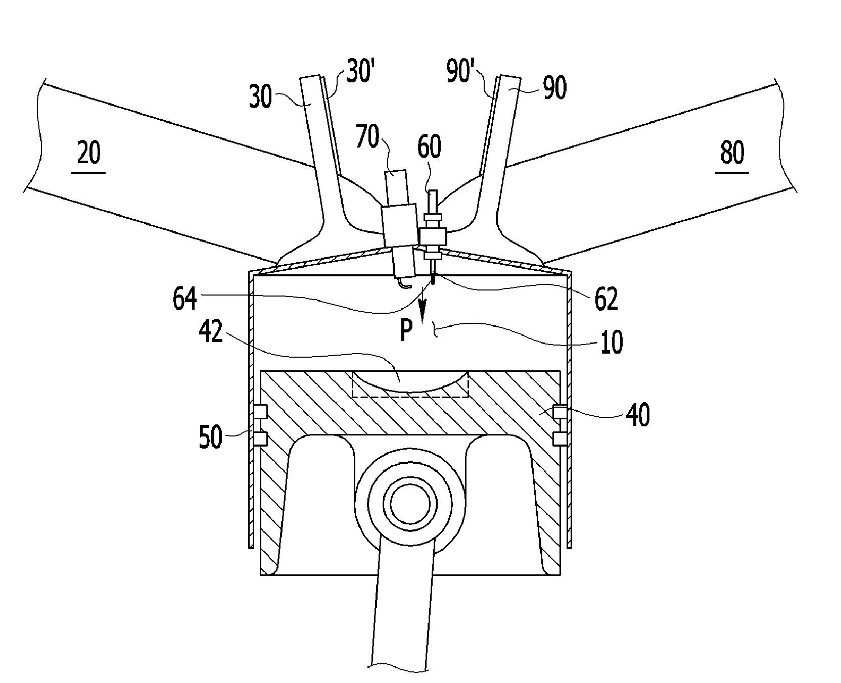
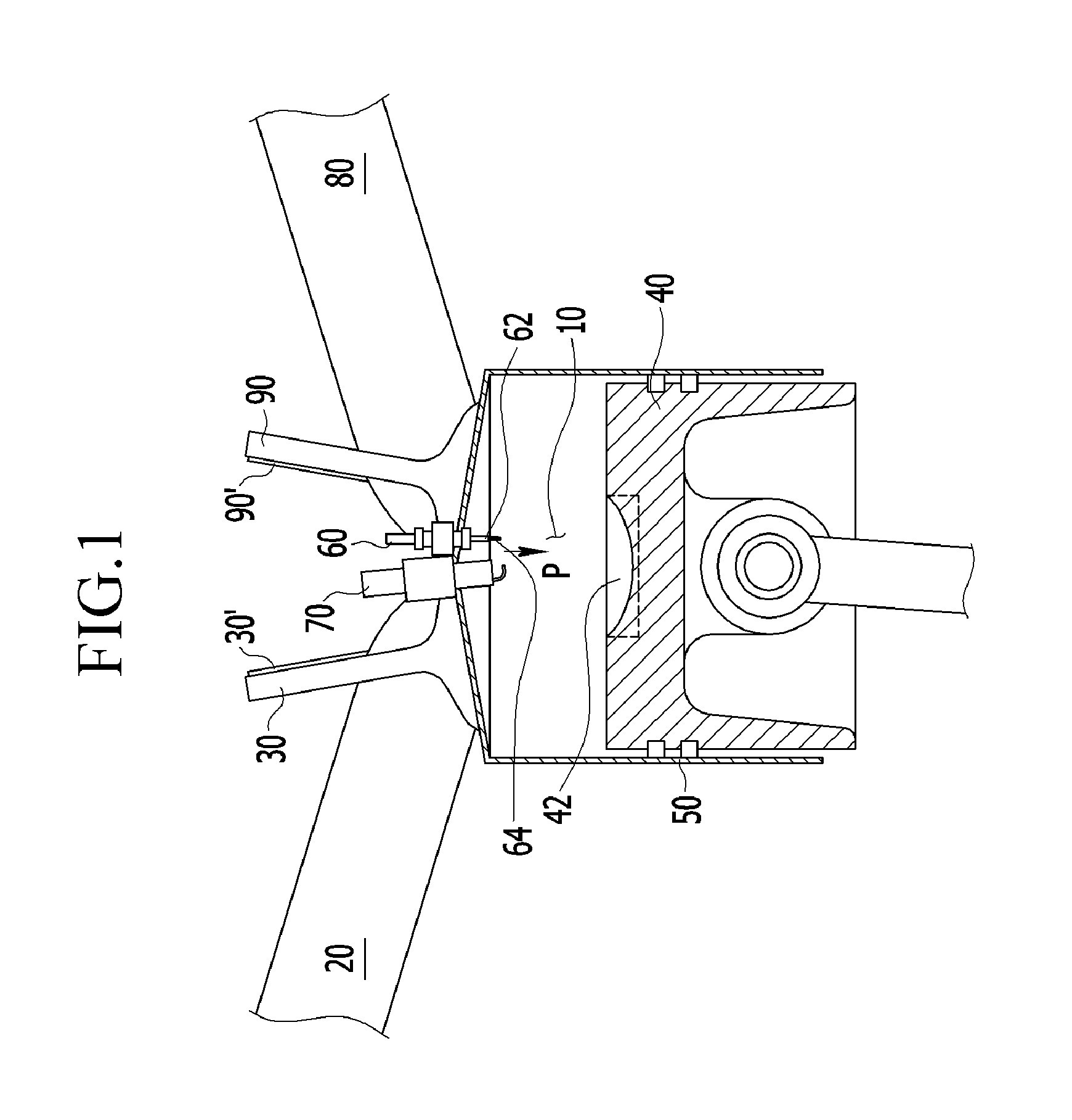
[0045]A compression ignition gasoline engine according to various embodiments of the present invention, as shown in FIG. 1, includes a combustion chamber 10, at least a pair of intake ports 20, an intake valve 30 positioned at the inlet of the combustion chamber 10 in the downstream of the intake port 20, a piston 40, a cavity 42 form...


PUM


Abstract

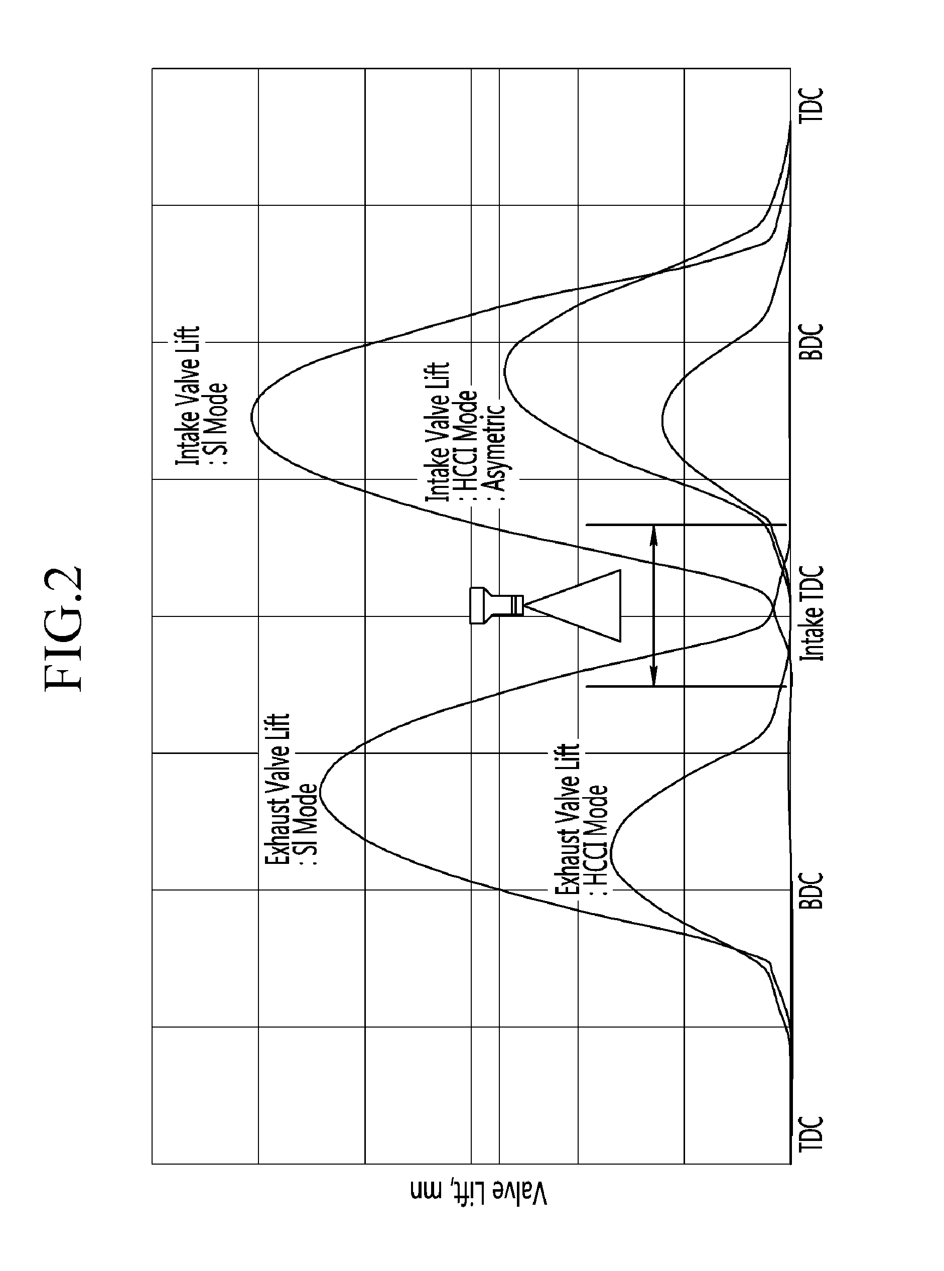
A compression ignition gasoline engine uses low-cetane number fuel, such as gasoline. The engine includes a combustion control device having an injector directly injecting fuel into a combustion chamber, intake and exhaust valves, and a variable valve device changing a valve timing, in which the compression ignition gasoline engine includes: at least two intake valves and two exhaust valves; a spark plug positioned at the center portion of the combustion chamber; and an injector positioned adjacent to the spark plug toward the center portion of the combustion chamber, in which the exhaust valve is a symmetric valve lift in which the lift and the opening section of the tow exhaust valves are the same in low lift, and the intake valve is an asymmetric valve lift in which the lift and the opening of the two intake valves are different in the low lift.

Description

CROSS-REFERENCE TO RELATED APPLICATION[0001]This application claims priority to and the benefit of Korean Patent Application No. 10-2009-0109303 filed in the Korean Intellectual Property Office on Nov. 12, 2009, the entire contents of which are incorporated herein by reference.BACKGROUND OF THE INVENTION[0002]1. Field of the Invention[0003]The present invention relates to a gasoline engine. More particularly, the present invention relates to a compression ignition gasoline engine using low-cetane number fuel, such as gasoline.[0004]2. Description of the Related Art[0005]In general, a gasoline direct injection engine equipped with a solenoid-typed in-ward injector and two-stage variable valve lift for maximizing the internal ERG is applied to gasoline Controlled Auto Ignition (CAI) engines in order to generate self-ignition, and the fuel is injected one time in a recompression process or two times in the recompression process and an intake process.[0006]In the two-time injection, as ...

Claims


Application Information

Patent Timeline
Patent Type & Authority Patents(United States)
IPC IPC(8): F02B1/12F02D19/08
CPCF02B17/005F02B23/101F02D13/0207F02D41/402Y02T10/125Y02T10/18F02B1/12Y02T10/12F02P15/08F02D41/3041F02D13/0257F02B23/10F01L13/00F02D13/02F02B11/00
Inventor LEE, JU HUNCHA, JEONG HWAKONG, JIN-KOOKKIM, YOUNG NAM
Owner HYUNDAI MOTOR CO LTD
Learn More