
Angular velocity detection apparatus

a detection apparatus and angular velocity technology, applied in the direction of instruments, speed/acceleration measurement, device material selection, etc., can solve the problems of impairing the detection sensitivity of the gyro sensor with respect to a variation in angular velocity, unable to accurately obtain and unable to accurately detect the yaw angle of the motorcycle. , to achieve the effect of high accuracy, reduced error and high accuracy

Inactive Publication Date: 2011-10-18
SEIKO EPSON CORP
View PDF9 Cites 22 Cited by
  • Summary
  • Abstract
  • Description
  • Claims
  • Application Information

AI Technical Summary

Benefits of technology

The invention provides an angular velocity detection apparatus with high accuracy. It includes a sensor unit with first and second detection axes, a sensor output correction circuit, a sign determination circuit, and an amplitude calculation circuit. The sensor output correction circuit makes adjustments to the detection output of the sensors to compensate for errors caused by the sensor's orientation and the sensor's sensitivity. The sign determination circuit obtains the sign of the rotational direction of the angular velocity. The amplitude calculation circuit calculates the square sum average of the detection outputs of the sensors. The sensor unit is preferably a double-T-shaped gyro sensor with four detection arms and two detection axes. The angle formed by the first and detection axes is preferably 90 degrees ±2 degrees. The apparatus also includes a control circuit for adjusting the offset and sensitivity of the sensor output correction circuit. The sensor failure check circuit detects any failure in the sensor unit. The angular velocity detection apparatus can be used in a mobile unit to obtain the yaw angle and the roll angle of the mobile unit with high accuracy.

Problems solved by technology

While a gyro sensor is typically used to obtain the yaw angle, an accurate yaw angle may not be obtained depending on the type of the mobile unit.
Thus, when the motorcycle is banked, the angular velocity detection axis is tilted, thereby failing to accurately obtain the yaw angle of the motorcycle.
This impairs the detection sensitivity of the gyro sensors with respect to a variation in angular velocity.
Therefore, the detection sensitivity of the sensor is originally low.
For this reason, with regard to the first related-art example, it is difficult to set a large angle for the tilt angle between the two gyro sensors in terms of the detection sensitivity.
However, if this method is used, the size of the gyro sensor is increased.
Also, in the first related-art example, the angular velocity detection axis of each tuning-fork gyro sensor extends in a direction in which a vibration arm thereof extends; therefore, the height (size) of the navigation system itself is unavoidably increased.
Thus, the signal-to-noise (S / N) ratio deteriorates, resulting in a reduction in detection accuracy.
Therefore, a difference in sensitivity between the gyro sensors causes an error in turn angular velocity, resulting in a reduction in accuracy of the navigation system.
This results in an increase in manufacturing cost.
Thus, if a failure occurs in the sensor unit, the failure is detected.

Method used


Image

  • Angular velocity detection apparatus
  • Angular velocity detection apparatus
  • Angular velocity detection apparatus

Examples


Embodiment Construction

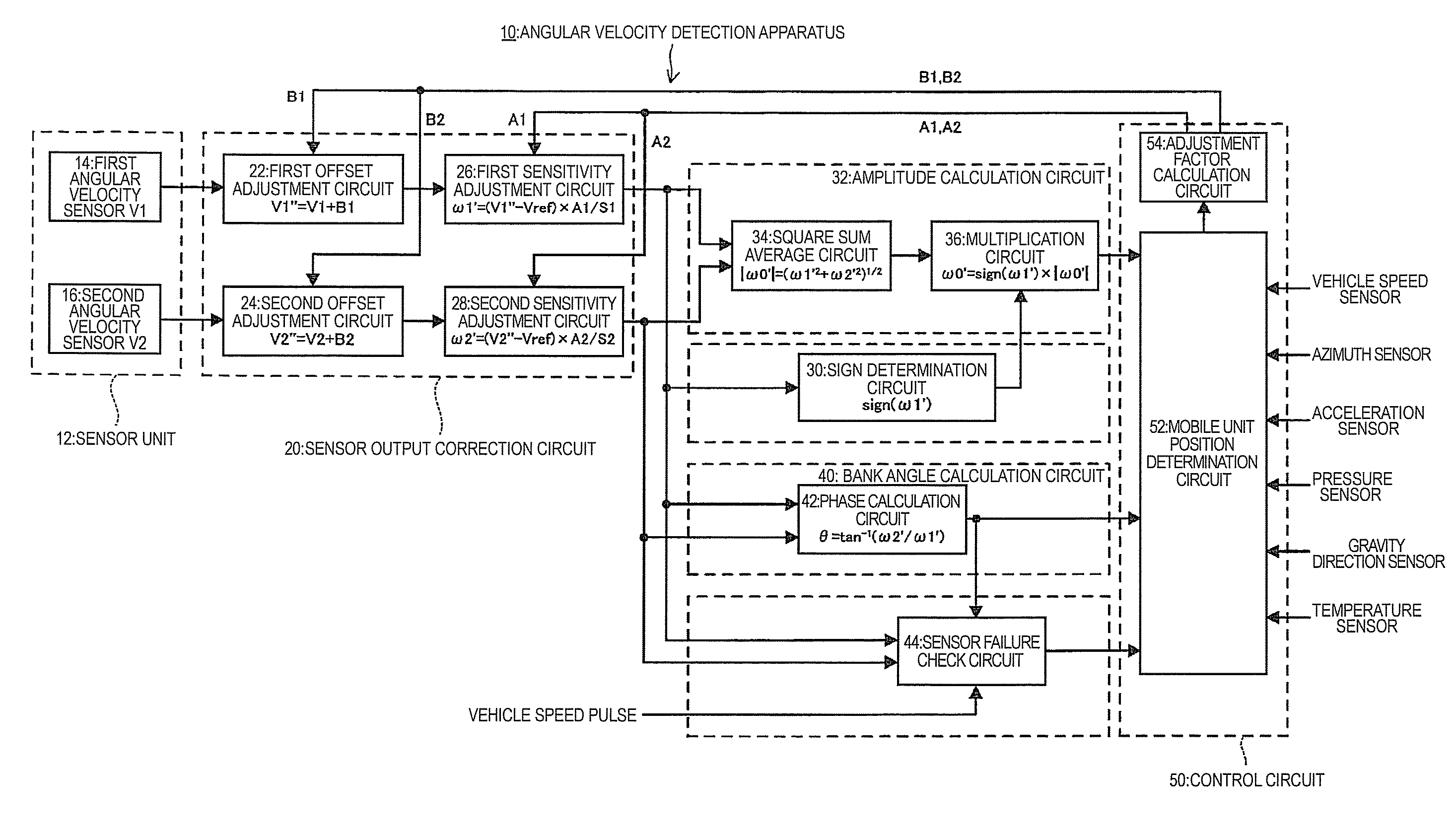
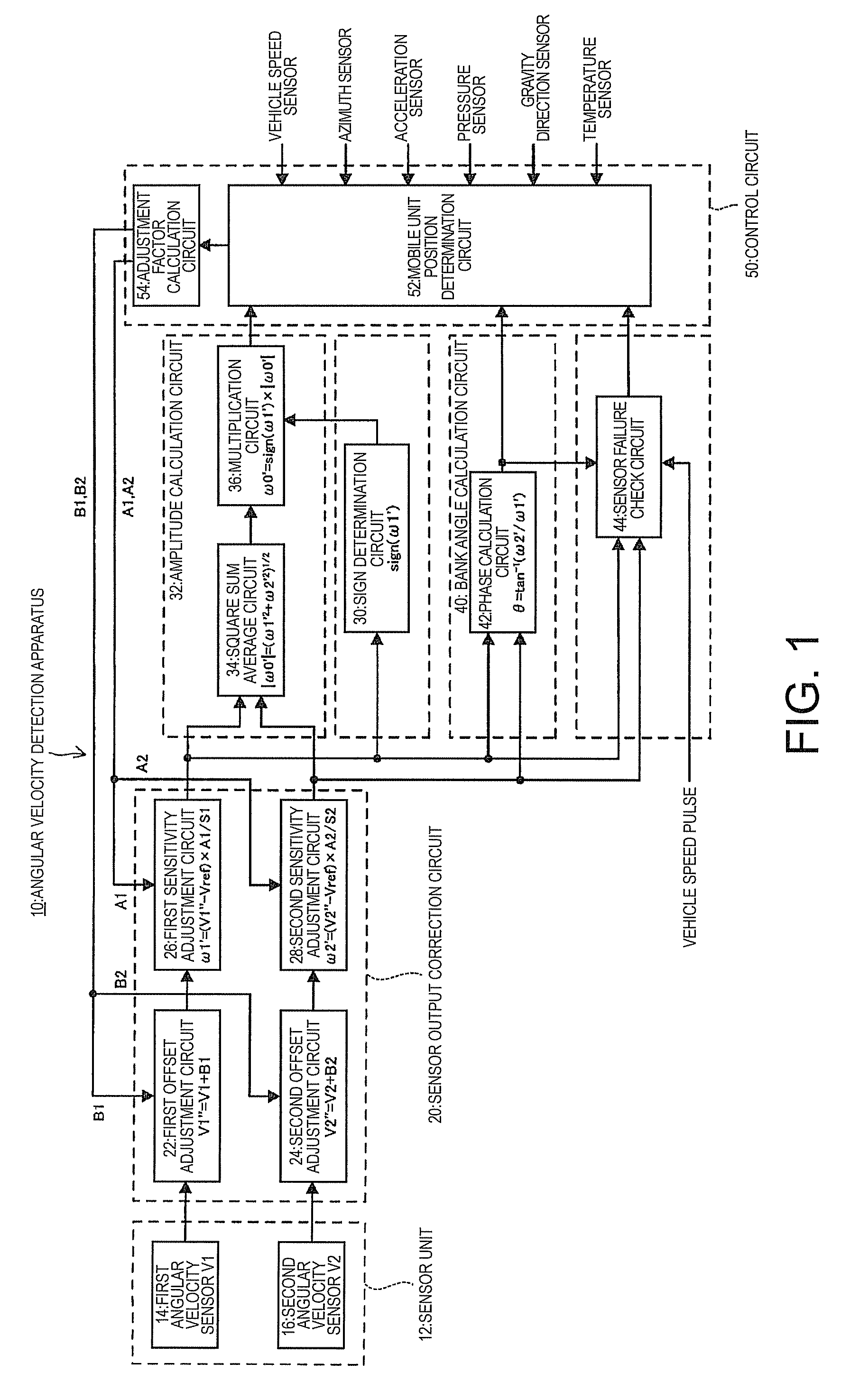
[0029]An angular velocity detection apparatus according to an embodiment of the invention will now be described. FIG. 1 is a block diagram of the angular velocity detection apparatus according to this embodiment. An angular velocity detection apparatus 10 includes a sensor unit 12, a sensor output correction circuit 20, a sign determination circuit 30, an amplitude calculation circuit 32, a bank angular velocity calculation circuit 40, a sensor failure check circuit 44, and a control circuit 50. The outline configuration of these circuits and like is as follows. That is, the sensor unit 12 includes first and second detection axes serving as angular velocity detection axes, which intersect each other. The sensor output correction circuit 20 makes an offset adjustment and a sensitivity adjustment to a detection output of an angular velocity around the first detection axis and a detection output of an angular velocity around the second detection axis outputted by the sensor unit 12.

[00...


PUM


Abstract

An angular velocity detection apparatus includes: a sensor unit having first and second detection axes serving as angular velocity detection axes, the first and second detection axes intersecting each other; a sensor output correction circuit for making at least one of an offset adjustment and a sensitivity adjustment to a detection output of an angular velocity around the first detection axis and a detection output of an angular velocity around the second detection axis; a sign determination circuit for obtaining a sign of a rotational direction of an angular velocity on any one of the first and second detection axes; and an amplitude calculation circuit for multiplying a square sum average of detection outputs of angular velocities around the first and second detection axes outputted by the sensor output correction circuit and a sign outputted by the sign determination circuit.

Description

BACKGROUND[0001]1. Technical Field[0002]The present invention relates to an angular velocity detection apparatus.[0003]2. Related Art[0004]To detect the behavior of a mobile unit, which is moving, with high accuracy so that the detected behavior is used by a navigation system, a safety device, a mobile data collector, or the like, the yaw angle and bank (roll) angle of the mobile unit must be obtained. While a gyro sensor is typically used to obtain the yaw angle, an accurate yaw angle may not be obtained depending on the type of the mobile unit. For example, if the mobile unit is a motorcycle, a gyro sensor is fixed to the body of the motorcycle. Thus, when the motorcycle is banked, the angular velocity detection axis is tilted, thereby failing to accurately obtain the yaw angle of the motorcycle.[0005]In the case of a motorcycle or the like, the roll angle significantly varies when the motorcycle or the like is moving, as described above, and the yaw angle is influenced by the rol...

Claims


Application Information

Patent Timeline
Patent Type & Authority Patents(United States)
IPC IPC(8): G01C19/00G01P3/04G01P21/00G01C19/56G01C19/5614G01C19/5621H01L41/08H01L41/18
CPCG01C19/5607G01C21/16
Inventor SATO, KENJI
Owner SEIKO EPSON CORP
Learn More