
Coil energization apparatus and method of energizing a superconductive coil

a superconducting coil and energizing technology, which is applied in the direction of superconducting magnets/coils, using reradiation, magnetic materials, etc., can solve the problems of limiting the maximum current, limiting the design of superconducting magnets, and undesirable reliance on the number of turns of superconducting wires, etc., to achieve the effect of improving the energizing efficiency

Inactive Publication Date: 2011-10-11
SIEMENS PLC
View PDF11 Cites 0 Cited by
  • Summary
  • Abstract
  • Description
  • Claims
  • Application Information

AI Technical Summary

Benefits of technology

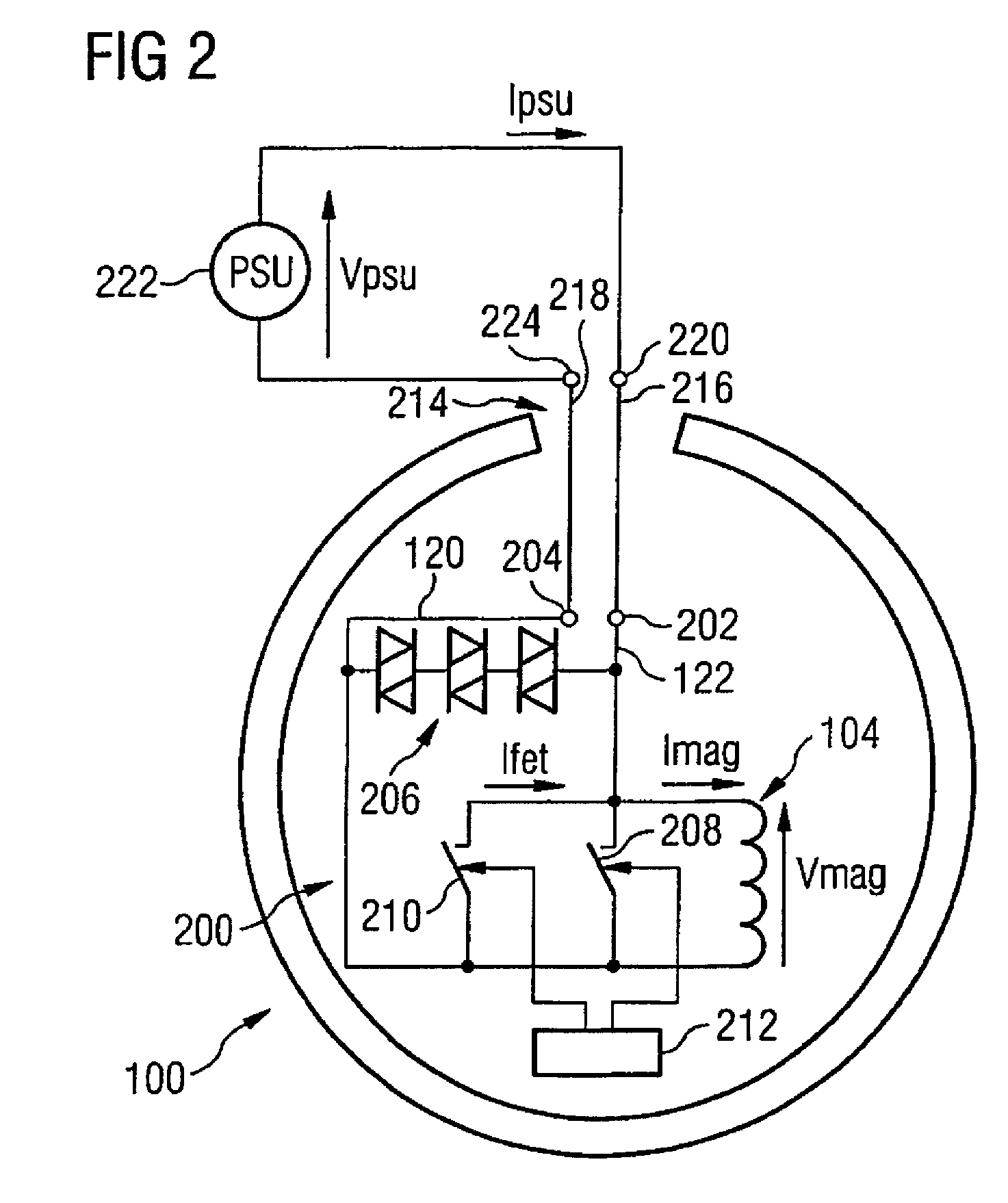
"The present invention provides a coil energization apparatus for a superconducting magnet that improves energy efficiency. This is achieved by a method and arrangement for introducing current into the magnet using a controlled switch and a pulsed current. The controlled switch is controlled to be in an ON state when current is not flowing through the terminals, and the pulsed current is applied to the terminals until it reaches a desired level. Once the desired level is reached, the controlled switch is maintained in an ON state until the superconducting switch becomes superconducting. This method reduces current loss and allows for increased operating current, resulting in a reduction of materials costs and process time. It also reduces heat leak through the current leads and allows for the use of cheaper materials for certain parts of the magnet. Additionally, the invention provides a switching device in parallel with the superconducting magnet to protect the current lead in case of fault conditions."

Problems solved by technology

Consequently, design of the superconducting magnet is constrained by limitations associated with the Current Lead in the following ways.
Firstly, the Current Lead limits the maximum current at which the superconducting magnet can operate.
Reliance on the number of turns of superconducting wire used is, however, undesirable because the superconducting wire is costly and manufacturing process time is, in part, a function of the number of turns of the coils of the superconducting magnet that has to be provided during manufacture.
Furthermore, when the Current Lead is a so-called fixed Current Lead, i.e. a Current Lead that remains in place after the superconducting magnet has been energized, heat leak is known to occur through the persistent Current Leads.
From a design perspective, the amount of heat leak that can therefore be tolerated from other parts of the superconducting magnet unit, for example suspension components of the superconducting magnet unit, is limited.
The use of more thermally efficient materials for the other parts of the superconducting magnet unit is therefore necessitated and this is costly, because whilst, in some cases, the cost of the materials is low, complexity of fitting the materials can be high.
However, the minimization of the heat leak is at the expense of providing access to a connector arrangement to connect the demountable Current Leads to the superconducting magnet and hence the need to expose the superconducting magnet to atmosphere.
Consequently, problems arise when trying to connect the demountable Current Lead to the superconducting magnet due to formation of ice in the connector arrangement provided.
Formation of ice within the superconducting magnet unit as a result of the superconducting magnet being exposed to atmosphere is an even greater and particularly costly problem associated with the use of the demountable Current Lead, because the ice formed influences interaction between the coils of the superconductive magnet and a supporting former of the coils resulting in the superconductive magnet being unable to achieve a desired operating field.
In more extreme cases, the ice can block the exit of the cryogen with undesirable effects.
However, as the HTS Current Leads are formed from a superconducting material, the use of the HTS Current Leads introduces a risk of the HTS material forming the Current Lead “quenching”, if the current flowing through the HTS Current Leads results in the so-called “critical surface” (characterizing the superconducting material from which the HTS Current Leads are formed) being reached or exceeded.
Boil-off is undesirable as the cryogen is wasted if no recovery system is in place, the cryogen being an expensive commodity.

Method used


Image

  • Coil energization apparatus and method of energizing a superconductive coil
  • Coil energization apparatus and method of energizing a superconductive coil
  • Coil energization apparatus and method of energizing a superconductive coil

Examples


Embodiment Construction

[0019]Throughout the following description identical reference numerals will be used to identify like parts.

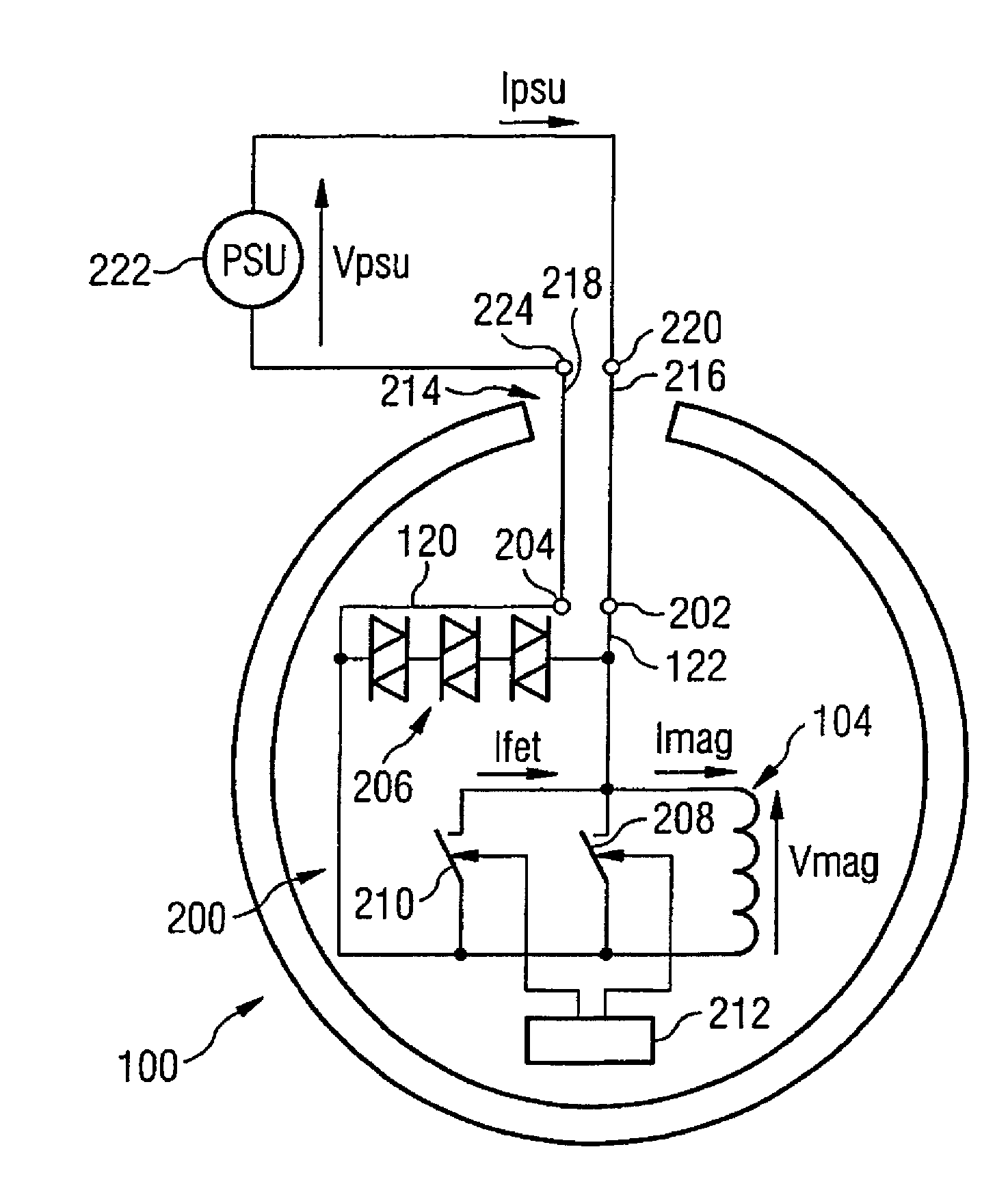
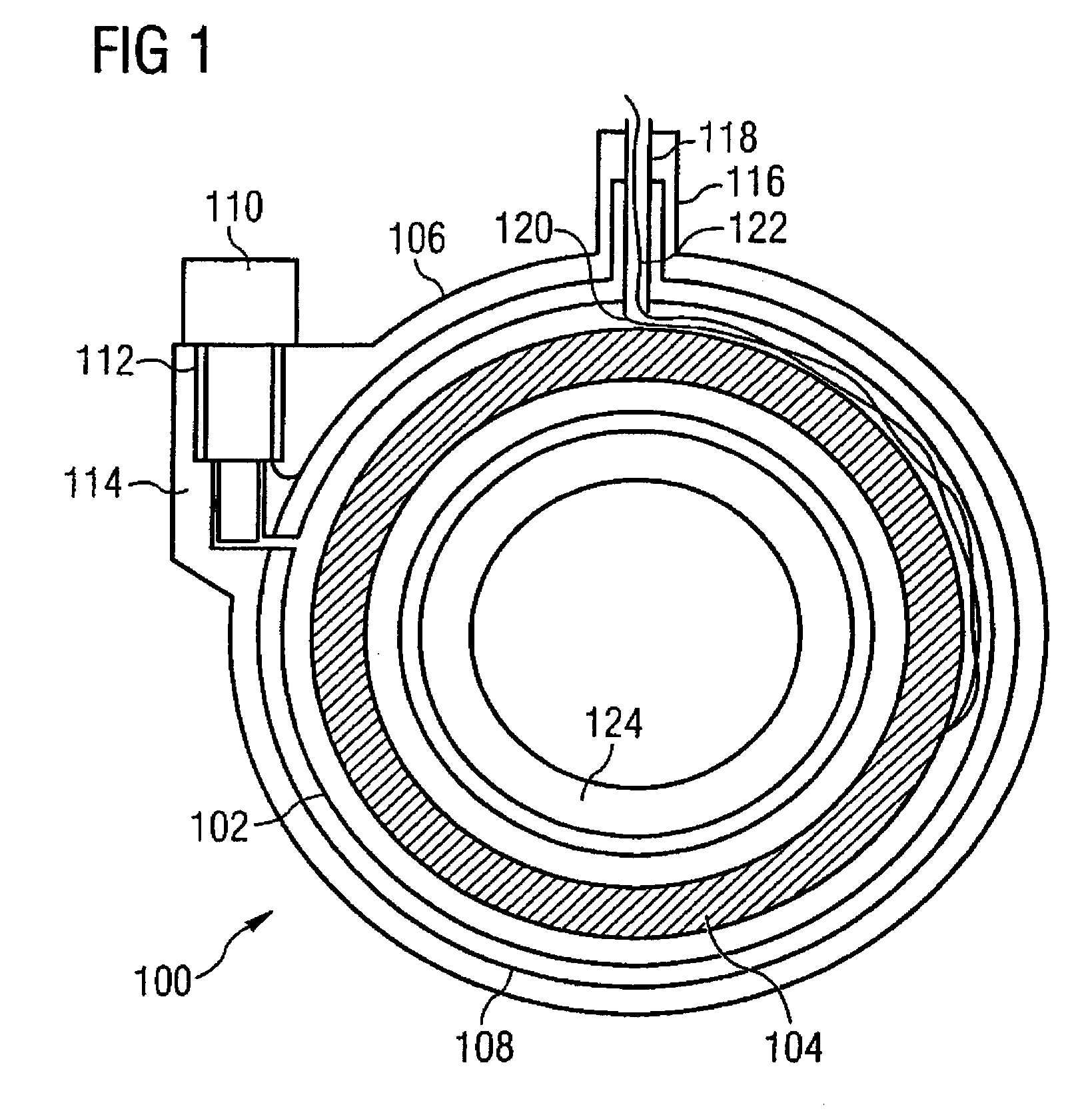
[0020]Referring to FIG. 1, a tomography system, for example a Magnetic Resonance Imaging (MRI) system, comprises a superconductive magnet unit 100 having a cryostat including a cryogen vessel 102. A cooled superconductive magnet 104 is provided within the cryogen vessel 102, the cryogen vessel 102 being retained within an Outer Vacuum Chamber (OVC) 106. One or more thermal radiation shields 108 are provided in a vacuum space between the cryogen vessel 102 and the OVC 106. In this example, a refrigerator 110 is mounted in a refrigerator sock 112 located in a turret 114 towards the side of the cryostat, the refrigerator 110 being provided for the purpose of maintaining the temperature of a cryogen provided in the cryogen vessel 102. An access turret 116 is provided at the top of the cryostat, the access turret 116 retaining a vent tube 118 that serves as an access neck. The refr...


PUM


Abstract

A coil energizing apparatus has a superconducting energization power supply having an output port. The power supply is arranged to generate, when in use, a pulsed output current signal at the output port.

Description

BACKGROUND OF THE INVENTION[0001]1. Field of the Invention[0002]The present invention relates to a coil energization apparatus of the type that, for example, is used to provide a superconductive coil with electrical current in order to achieve generation of a magnetic field, such as a static magnetic field. The present invention also relates to a method of energizing a superconductive coil of the type that, for example, is used to provide the superconductive coil with electrical current in order to achieve generation of a magnetic field, such as a static magnetic field.[0003]2. Description of the Prior Art[0004]In the field of nuclear Magnetic Resonance Imaging (MRI), a magnetic resonance imaging system typically comprises a superconducting magnet, a gradient coil system, field coils, shim coils and a patient table. The superconducting magnet is provided in order to generate a strong uniform static magnetic field, known as the B0 field, in order to polarize nuclear spins in an objec...

Claims


Application Information

Patent Timeline
Patent Type & Authority Patents(United States)
IPC IPC(8): G01V3/00
CPCG01R33/3815H01F6/006
Inventor HICKMAN, KEVIN JONATHAN
Owner SIEMENS PLC
Learn More