Liquid crystal display panel with electrostatic protection structure
a technology of electrostatic protection and lcd panel, which is applied in the direction of instruments, non-linear optics, optics, etc., can solve the problems of poor reliability of malfunction or even damage of internal circuits of substrates, and almost all electronic products are subject to the interference of electrostatic discharge or even damaged, so as to enhance the electrostatic protection of lcd panel and increase product competitiveness
- Summary
- Abstract
- Description
- Claims
- Application Information
AI Technical Summary
Benefits of technology
Problems solved by technology
Method used
Image

Examples
first embodiment
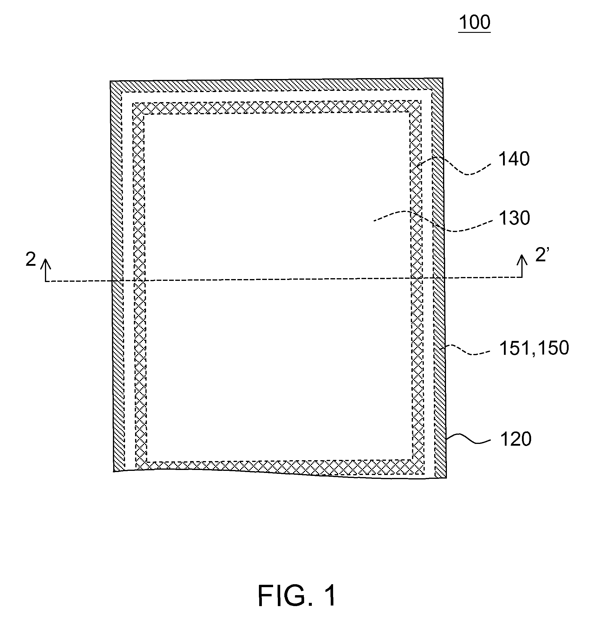
[0024]In the first embodiment, the electrostatic protection structure includes a first line. The first substrate is a TFT substrate, the second substrate is a color filter substrate, and the first line is disposed on the TFT substrate and surrounds the edge of the TFT substrate.
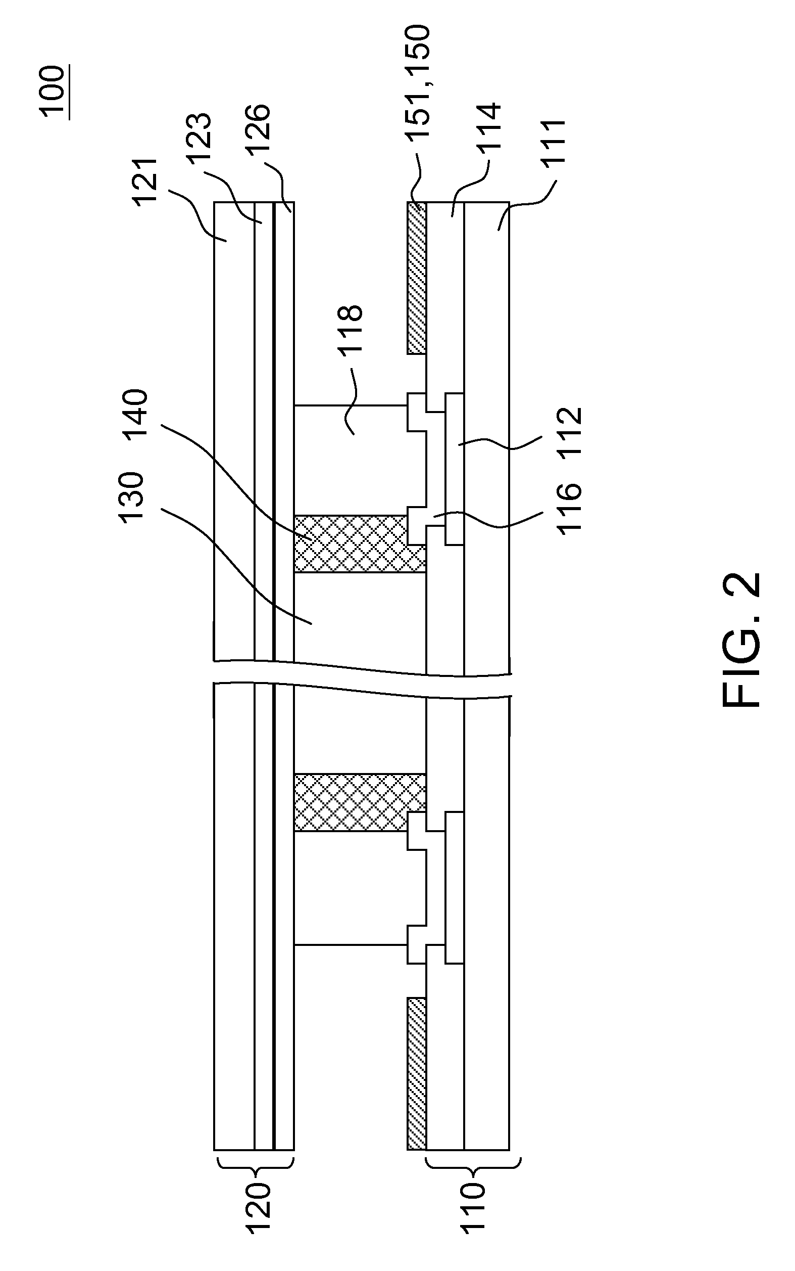
[0025]Referring to both FIG. 1 and FIG. 2, a partial diagram of an LCD panel according to a first embodiment of the invention is shown in FIG. 1, and a cross-section view of the LCD panel in FIG. 1 along the cross-sectional line 2-2′ is shown in FIG. 2. The LCD panel 100 includes a TFT substrate 110, a color filter substrate 120, a liquid crystal layer 130, a sealant 140 and an electrostatic protection structure 150. The TFT substrate 110 and the color filter substrate 120 are disposed in parallel to each other. The sealant 140 seals the liquid crystal layer 130 between the TFT substrate 110 and the color filter substrate 120. The inner area of the sealant 140 is a display area of the LCD panel 100. The displ...
second embodiment
[0030]The second embodiment differs from the first embodiment in the disposition relationship between the common electrode line and the electrostatic protection structure. In the second embodiment, the electrostatic protection of the LCD panel is further enhanced by changing the disposition relationship between the common electrode line and the electrostatic protection structure. Referring to FIG. 5, a cross-section view of an LCD panel according to a second embodiment of the invention is shown. As FIG. 5 can be viewed as a modification of FIG. 2, similar components in FIG. 5 are designated with similar numbers and are not repeatedly described herein.
[0031]In FIG. 5, the first line 251 is partially overlapped and electrically insulated from the common electrode line 212, so as to form a capacitor structure at the overlapped part between the first line 251 and the common electrode line 212. When electrostatic discharge occurs, the capacitor structure generates capacitor coupling effe...
third embodiment
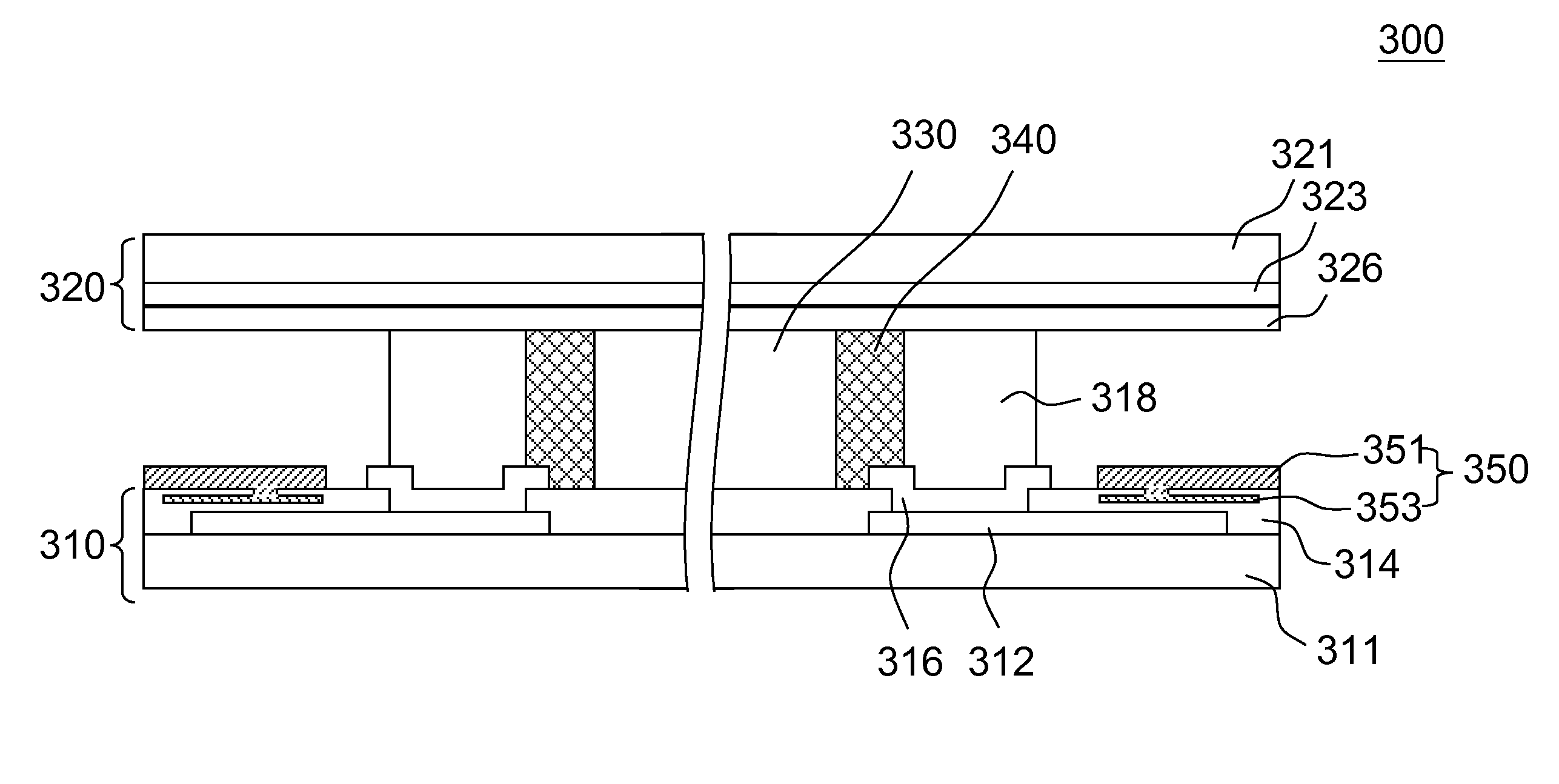
[0032]The third embodiment differs from the second embodiment in that a metal layer is disposed between the first line and the common electrode line. In the present embodiment of the invention, the metal layer is used for increasing the equivalent capacitance of the capacitor structure so as to further enhance the electrostatic protection of the LCD panel. Referring to FIG. 6, a cross-section view of an LCD panel according to a third embodiment of the invention is shown. As FIG. 6 can be viewed as a modification of FIG. 5, similar components in FIG. 6 are designated with similar numbers and are not repeatedly described herein.
[0033]In FIG. 6, the electrostatic protection structure 350 further includes a metal layer 353 positioned between the first line 351 and the common electrode line 312, and a part of the metal layer 353 is covered by the insulating layer 314. The metal layer 353 is electrically connected to the first line 351 and is partially overlapped and electrically insulate...
PUM
| Property | Measurement | Unit |
|---|---|---|
| electric | aaaaa | aaaaa |
| electrically | aaaaa | aaaaa |
| electrostatic charges | aaaaa | aaaaa |
Abstract
Description
Claims
Application Information
 - R&D
- Intellectual Property
- Life Sciences
- Materials
- Tech Scout
- Unparalleled Data Quality
- Higher Quality Content
- 60% Fewer Hallucinations
Browse by: Latest US Patents, China's latest patents, Technical Efficacy Thesaurus, Application Domain, Technology Topic, Popular Technical Reports.
© 2025 PatSnap. All rights reserved.Legal|Privacy policy|Modern Slavery Act Transparency Statement|Sitemap|About US| Contact US: help@patsnap.com