Polymerisation process

a technology of polymerisation and process, applied in the field of polymerisation process, can solve the problems of compromising the efficiency of solids concentration and particle size separation, the inability to provide a means of varying the solids concentration of the feed to the concentrator independently, and the inability to achieve the effect of improving the efficiency and reliability of separation, reducing the risk of affecting the operation of hydrocyclones, and reducing the risk of affecting the operation

Inactive Publication Date: 2011-09-13
INEOS EURO LTD
View PDF4 Cites 0 Cited by
  • Summary
  • Abstract
  • Description
  • Claims
  • Application Information

AI Technical Summary

Benefits of technology

[0009]The provision of a recycle capability to the feed of the concentrator downstream of the polymerisation zone enables the volumetric flowrate and / or solids loading of the polymer slurry fed to or from the concentrator to be maintained within a much narrower range than would otherwise be possible over the typical range of plant operating conditions. Thus the invention provides a way of allowing a concentrator to operate within its optimum operating window whilst receiving polymer slurry which has been withdrawn from a polymerisation reactor over a much wider range of flowrates and slurry concentrations.
[0018]In order to minimize the heat input required in the downstream processing sections it is most preferred that the solids-rich stream withdrawn from the concentrator is maintained at as great a concentration as possible whilst still maintaining a reliable flow. A solids concentration of greater than 65 wt % is most preferred. The present invention enables the concentration of the solids-rich stream withdrawn from the concentrator to equal or exceed the concentration achieved with a settling leg.
[0024]Whilst the polymer slurry withdrawal from the polymerisation zone is preferably from a region having higher pressure than the pressure of any streams returned to the polymerisation zone from the concentrator, it is preferred that a pump is employed to improve the efficiency and reliability of the separation in the concentrator. The recycle stream or streams may be driven by one or more pumps, preferably located in the polymer slurry feed stream for the concentrator downstream of the introduction point of the recycle stream. The pump is preferably a single centrifugal type pump.
[0025]The present invention may be used in systems that operate either continuous or discontinuous withdrawal of slurry from the polymerisation zone. Operation of hydrocyclones can be particularly unreliable and inefficient when operating with an intermittent or highly variable feed flow, such as is the case when withdrawing the polymer slurry from the polymerisation reactor discontinuously, and this invention may provide significant benefits for such an arrangement. When operating in this mode, the present invention permits the flowrate of the solids-rich stream recycled from the concentrator to be controlled or varied in order to minimise fluctuations in the feed flowrate to the concentrator.

Problems solved by technology

However whilst centrifugal concentrating devices are well known, the design of such devices itself is typically such that the operation can only be optimised over a limited range of design operating conditions.
When operating away from such design operating conditions, particularly during start-up or grade transitions, not only is the efficiency of the solids concentration and particle size separation compromised but also the concentrating device and its associated pipework become much more susceptible to blockage, mainly due to polymerisation of active polymer present in the stream being concentrated.
It is known in U.S. Pat. No. 3,816,383 to recycle part of the solids-rich stream produced by a concentrating device directly back into the polymerisation zone; however this process does not provide a means of varying the solids concentration of the feed to the concentrator independently of the solids concentration in the off-take stream from the polymerisation zone.
In particular it cannot provide the concentrator with a feed stream that is more concentrated in solids than in the stream withdrawn from the polymerisation zone.
As above, this does not permit any control of the concentration of the feed entering the concentrator itself.

Method used


Image

  • Polymerisation process
  • Polymerisation process

Examples


example 1

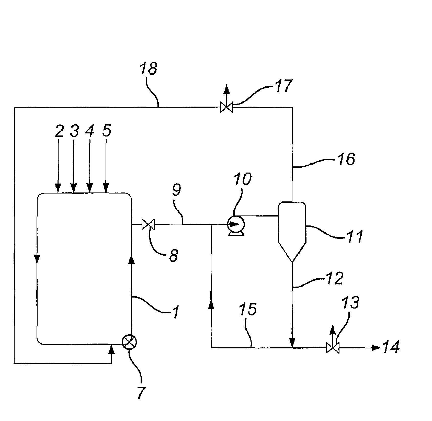
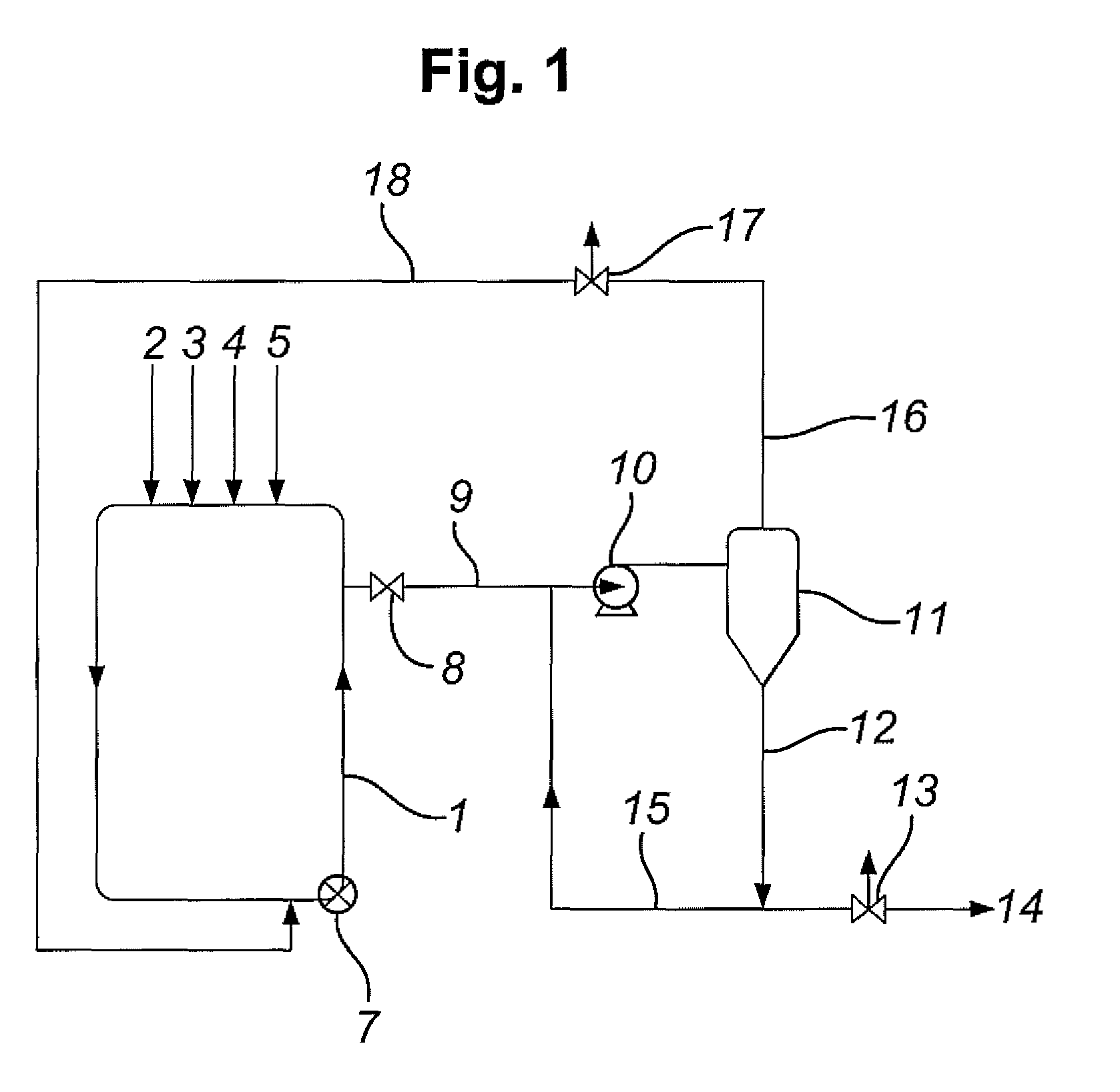
[0041]This example is an arrangement as shown in FIG. 1, in which a polymer-containing slurry is discharged from a reactor 1 into a hydrocyclone 11 via line 9. The solids-lean stream from the hydrocyclone is recycled to the reactor via line 16, whilst the solids-rich stream from the hydrocyclone is separated into two flows, one of which passes downstream via line 14, and the other of which is recycled into line 9 via line 15.

[0042]The production rate of the reactor is 10000 kg / h, and it has a solids concentration of 41 wt %. The conditions in the lines shown in FIG. 1 are given in Table 1 below.

[0043]

TABLE 1Line 9Line 9beforeafterrecycleLine 12Line 14Line 15Line 16recycleTotal slurry flowkg / h330003458018690158901431048889Liquid flowkg / h1947016080869073901078026859Solid flowkg / h1353018500100008500353022030Solids contentwt %41.053.554.054.025.045.1Vol flowratem3 / h57.755.430.025.527.783.1

In this Example, the hydrocyclone increases the solids concentration of the stream to be passed dow...

example 2

[0044]This Example shows how recycling part of the solids-rich flow from the hydrocyclone can enable a constant solids concentration to be maintained at the input into the hydrocyclone, despite different conditions in the stream exiting the reactor. In this Example, the solid flowrate leaving the reactor is higher than Example 1, but the solids concentration is lower.

[0045]

TABLE 2Line 9Line 9beforeafterrecycleLine 12Line 14Line 15Line 16recycleTotal slurry flowkg / h376104571018690270201891064620Liquid flowkg / h22940212608690125601425035500Solid flowkg / h14670244501000014460466029120Solids contentwt %39.053.554.054.025.045.1Vol flowratem3 / h66.673.230.043.336.6109.9


PUM

PropertyMeasurementUnit
Fractionaaaaaaaaaa
Fractionaaaaaaaaaa
Timeaaaaaaaaaa

Abstract

Olefin polymerisation process in which a slurry of olefin polymer is produced within a polymerisation zone, followed by withdrawing a polymer slurry stream from the polymerisation zone, and passing the polymer slurry stream through a transfer line to a centrifugal concentrating device which separates the polymer slurry stream into a solids-lean stream or streams each having a solids concentration less than that of the polymer slurry stream entering the concentrating device and a solids-rich stream or streams each having a solids concentration greater than that of the polymer slurry stream entering the concentrating device. At least part of the solids-rich stream or streams is recycled back into the polymer slurry stream upstream of the concentrating device and downstream of the polymerisation zone, and 2-60 vol % of the solids-rich slurry stream is recycled back into the polymer slurry stream upstream of the concentrating device.

Description

[0001]This application is the U.S. national phase of International Application No. PCT / EP2008 / 055815 filed 13 May 2008 which designated the U.S. and claims priority to European Patent Application No. 07252062.0 filed 18 May 2007, the entire contents of each of which are hereby incorporated by reference.[0002]The present invention is concerned with an improved process and apparatus for slurry phase olefin polymerisations.BACKGROUND OF THE INVENTION[0003]Slurry phase polymerisation of olefins is well known wherein an olefin monomer, and optionally olefin comonomer, are polymerised in the presence of a catalyst in a diluent in which the solid polymer product is suspended and transported.[0004]This invention is particularly related to polymerisation in a loop reactor where the slurry is circulated in the reactor typically by means of a pump or agitator. Liquid full loop reactors are well known in the art and are described for example in U.S. Pat. Nos. 3,152,872, 3,242,150 and 4,613,484....

Claims


Application Information

Patent Timeline
IPC IPC(8): C08F2/00C08F6/00
CPCC08F10/00C08F2/14C08F2/01C08F10/02C08F10/06
Inventor PARISEL, MARC J. G.WALWORTH, BRENT R.
Owner INEOS EURO LTD
Why Eureka
Try Eureka