Filtration apparatus

a technology of filtration apparatus and filtration device, which is applied in the direction of gravity filter, sedimentation settling tank, loose filtering material filter, etc., can solve the problems of limiting the effectiveness of current filtration device, limiting the space and weight requirements, and further waste disposal problems

Active Publication Date: 2011-09-06
KCC GROUP
View PDF80 Cites 28 Cited by
  • Summary
  • Abstract
  • Description
  • Claims
  • Application Information

AI Technical Summary

Benefits of technology

[0013]The discharge outlet may be provided with a filter screen which defines the chamber containing the second filter media. The chamber may retain a media support bed made up of a larger particulate material than the particulate material used for filtering, in order to inhibit loss of such fine media to the clean water side or blockage of the clean water collection screens, which may comprise small slots or holes.
[0031]In accordance with another feature of the present invention, the distribution of water to be filtered is controlled accurately, such that all areas of the filter bed receive as near as possible the same flow (flow sharing), thus avoiding channelling or flow taking the least line of resistance to the central collection screen. A further mechanical advantage is that the present invention excludes joints which are potential leak paths from the dirty water side to the clean water side, inside the housing (particularly where the housing is pressurised), ensuring therefore that no dirty water can leak to the clean water. Any such joints are preferably positioned on the outside of the vessel for maintenance reasons.

Problems solved by technology

The use of cartridge filter elements that require frequent cleaning or changing, although an efficient means of filtration, creates a waste stream of used cartridge elements which is a further waste disposal problem.
The space and weight requirements of current filtration devices is also becoming a limiting factor in expanding or new build water treatment facilities, particularly for use on offshore oil exploration and production platforms.
Although the better designs go a good way to answering some of the problems associated with radial filtration and the backwash of its media, they do have some features which limit their effectiveness, such as a peripheral inlet screen that defines an annulus to receive water to be filtered, and distribute it radially into the media bed.
This is undesirable as it will require a method of cleaning this screen or at least a strainer upstream of the filter to ensure that no particles larger than the screen gap size are delivered to the filter.
This can create large pressure drops and force fine suspended solids to migrate through the bed, particularly whilst the bed is in wash mode whilst on line.

Method used


Image

  • Filtration apparatus
  • Filtration apparatus
  • Filtration apparatus

Examples


Embodiment Construction

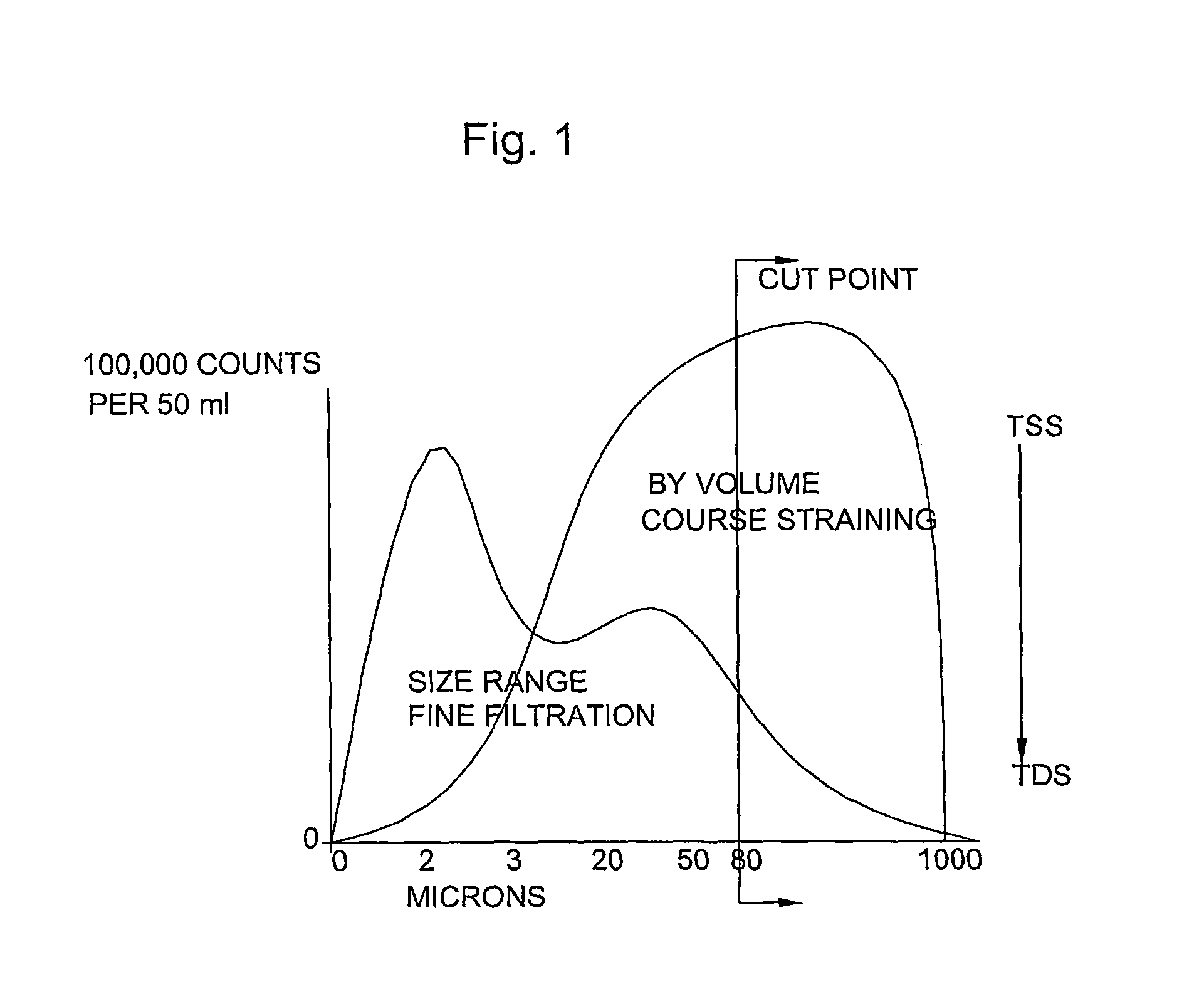
[0041]From the plot of FIG. 1 it can be seen that a lower number of larger particles account for the bulk of the volume of contaminants. In a conventional filtration process, it would be normal to attempt to remove the vast majority of these large particles at some cut off point, in this example around 80 microns and above with a coarse filter, so that any fine filtration would only need to remove smaller particles. The present invention seeks to achieve this degree of filtration with one filtration step.

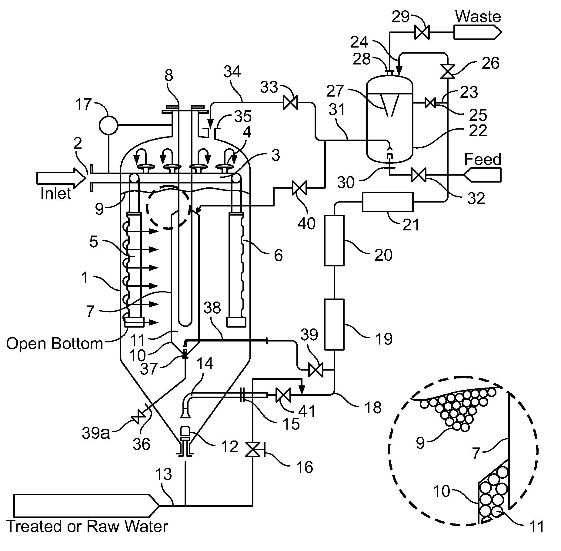
[0042]Referring to FIGS. 2 and 3, a pressure vessel or tank 1 has an inlet means 2 for raw water to be treated which connects with a distribution ring 3. The distribution ring 3 has a plurality of flow distribution heads 4, to distribute a portion of the inlet flow upwards to the top of the vessel 1, and a plurality of substantially vertical flow distribution tubes 5 which have distribution holes or slots 6 designed such that the flow of raw water is equally distributed and directed...


PUM

PropertyMeasurementUnit
diameteraaaaaaaaaa
diameteraaaaaaaaaa
particle sizeaaaaaaaaaa

Abstract

A radial or crossflow media filter comprising a housing such as a vessel or tank (1), the housing containing filter media (9), a contaminated flow inlet (2) and a discharge outlet (8), the inlet comprising a manifold (5) situated within the housing, the manifold (5) having flow outlets (6) which are directed laterally, away from the discharge outlet (8). The flow inlet may comprise a substantially vertically aligned elongate tubular manifold (5) with a plurality of flow distribution holes or slots disposed along its length. Furthermore, the discharge outlet (8) may be accessed through a chamber within the housing which contains a second filter media (11) which is of larger average particle size than the first filter media (9).

Description

BACKGROUND TO THE INVENTION[0001]There is a considerable need worldwide to generate more pure water for potable and industrial uses, which itself creates both domestic and industrial waste streams requiring further treatment prior to recycling or discharge to the environment. The use of cartridge filter elements that require frequent cleaning or changing, although an efficient means of filtration, creates a waste stream of used cartridge elements which is a further waste disposal problem.[0002]It is also known to carry out downflow and upflow filtration of suspended solids from a liquid stream using a granular media bed, either atmospherically in concrete, plastic, metal or GRP tanks or above atmospheric pressure inside a suitably designed pressure vessel manufactured in metal, plastic or GRP. Many variants are known in distribution and collection methodology, in the media selection, and in chemical enhancement and filtration velocities.[0003]The space and weight requirements of cur...

Claims


Application Information

Patent Timeline
Patent Type & Authority Patents(United States)
IPC IPC(8): B01D37/00B01D24/46B01D24/00B01D24/06B01D24/16
CPCB01D24/008B01D24/06B01D24/167B01D24/047B01D24/10B01D24/30B01D24/40B01D24/4689B01D29/90B01D35/22B01D27/02
Inventor PARKINSON, DAVID JOHN
Owner KCC GROUP
Why Eureka
Try Eureka