
Rotating union for a liquid cooled rotating X-ray target

a liquid cooled, rotating x-ray target technology, applied in the direction of x-ray tube cooling, x-ray tubes, mechanical equipment, etc., can solve the problems of rotating face seal mate, anode x-ray tube heat generation, leakage of coolant,

Active Publication Date: 2011-08-30
GENERAL ELECTRIC CO
View PDF9 Cites 6 Cited by
  • Summary
  • Abstract
  • Description
  • Claims
  • Application Information

AI Technical Summary

Benefits of technology

The solution effectively prevents coolant leakage, enhances the reliability and durability of the rotating union, and maintains operation under high G-loads, ensuring the integrity of the imaging system and its environment.

Problems solved by technology

Unfortunately these anode X-ray tubes tend to get heated while generating the X-rays.
The high G-loads may cause the rotating shaft coupled to the X-ray target to bend thereby causing the rotating face seal to misalign from the non-rotating face seal mate.
This may cause uneven wear resulting in leakage of coolant.
Additionally, a gap may be formed between the faces of the seals causing leakage of coolant.
Also, the liquid coolant for cooling various components of the X-ray tube may leak from the rotating union due to the design of the rotating union especially for rotating unions employing standard face seals.
Coolant leakage may also occur due to wear and tear of certain components or due to any malfunctioning of the rotating union.
The coolant leakage may be detrimental to the imaging system which includes the rotating union or to the environment in which the imaging system operates.
Furthermore, deflection of the shaft at the interface of a mechanical face seal may create pressure gradients that may in turn cause uneven wear, leakage and shorter life of a mechanical face seal.

Method used


Image

  • Rotating union for a liquid cooled rotating X-ray target
  • Rotating union for a liquid cooled rotating X-ray target
  • Rotating union for a liquid cooled rotating X-ray target

Examples


Embodiment Construction

[0016]Embodiments of the present invention relate generally to a rotating union for a liquid cooled X-ray target in medical imaging systems and more particularly to a rotating union for an X-ray target in X-ray tubes. An exemplary rotating union in X-ray tube based imaging systems such as a computed tomography system is presented.

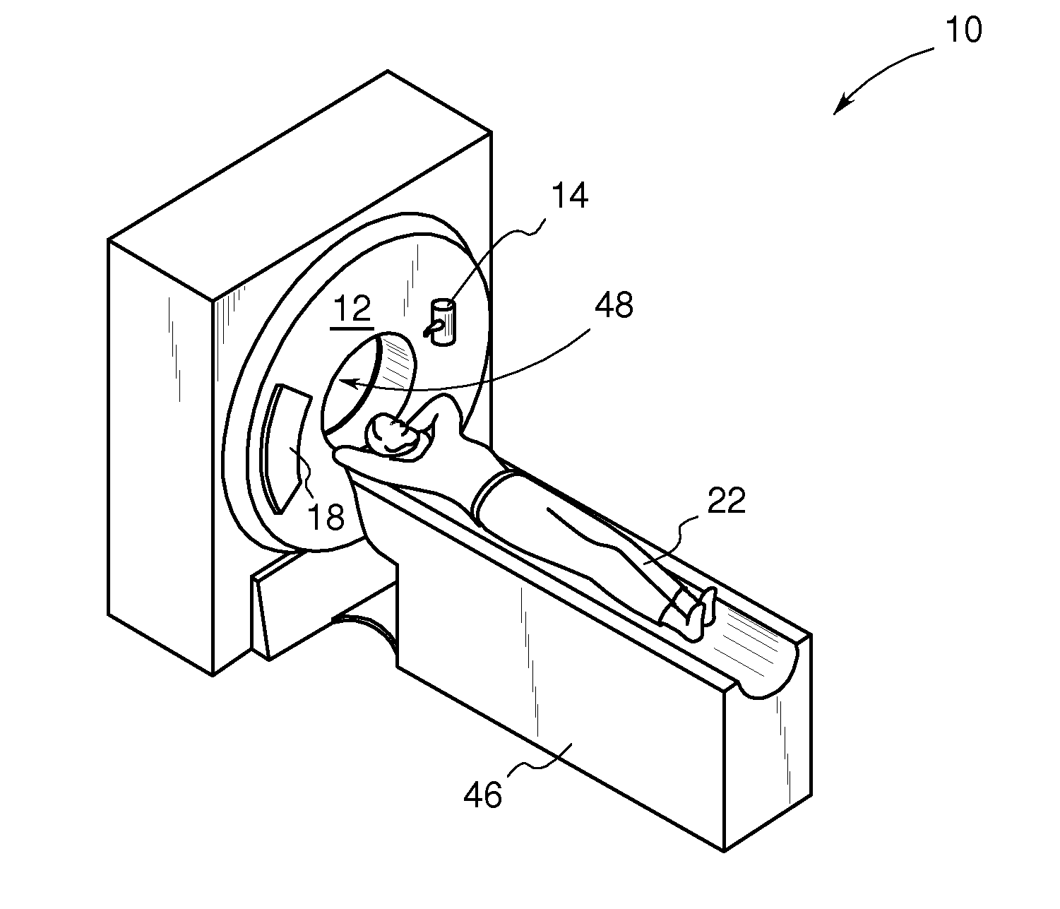
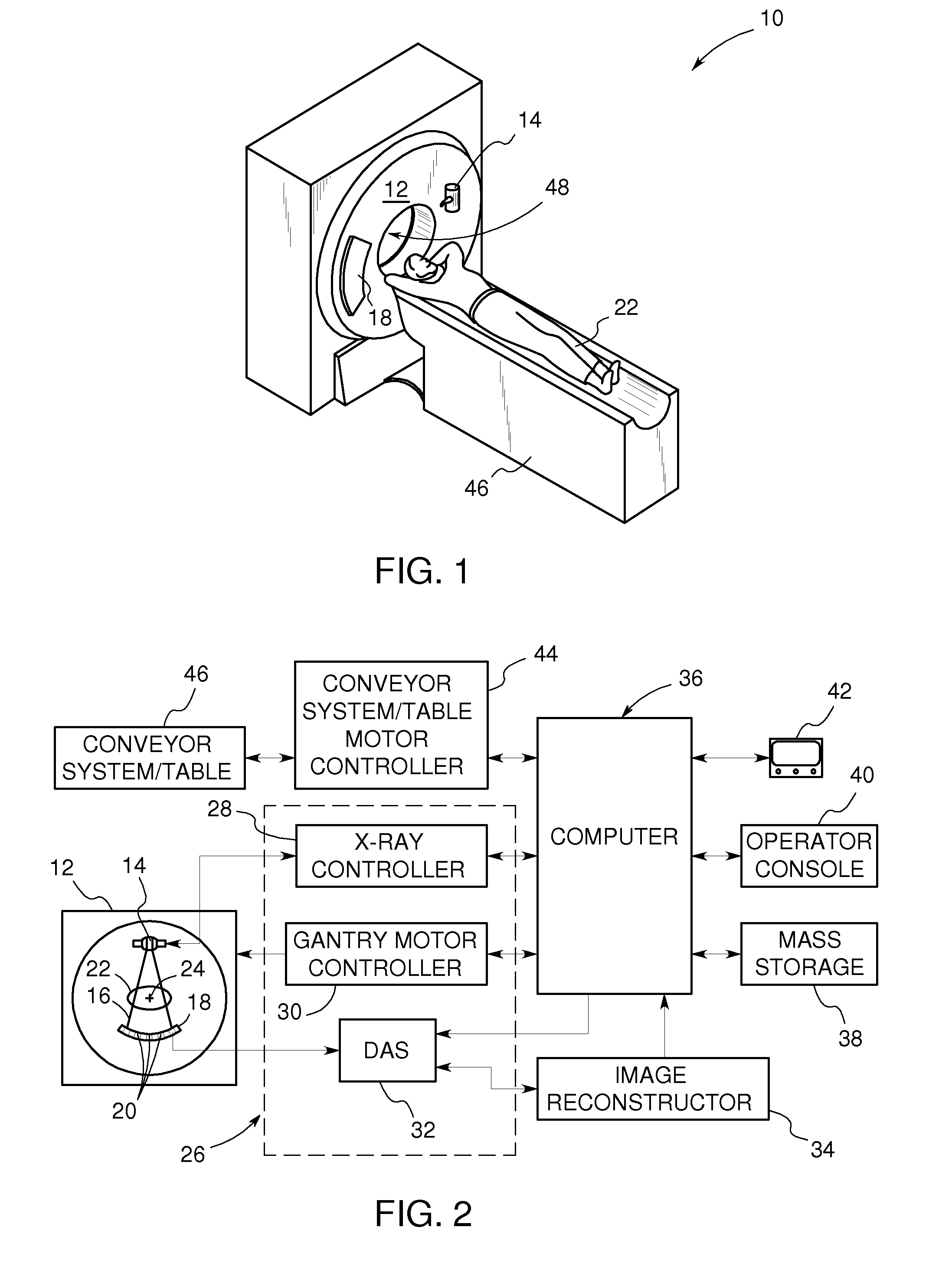
[0017]Referring now to FIGS. 1 and 2, a computed tomography (CT) imaging system 10 includes a gantry 12 representative of a “third generation” CT scanner. Gantry 12 has an X-ray source 14 that projects a beam of X-rays 16 towards a detector array 18 on the opposite side of gantry 12. In one embodiment, the gantry 12 may have multiple X-ray sources that project beams of X-rays. The detector array 18 is formed by a plurality of detectors 20 which together sense the projected X-rays that pass through an object to be imaged, such as a medical patient 22. During a scan to acquire X-ray projection data, the gantry 12 and the components mounted thereon rotate abou...


PUM


Abstract

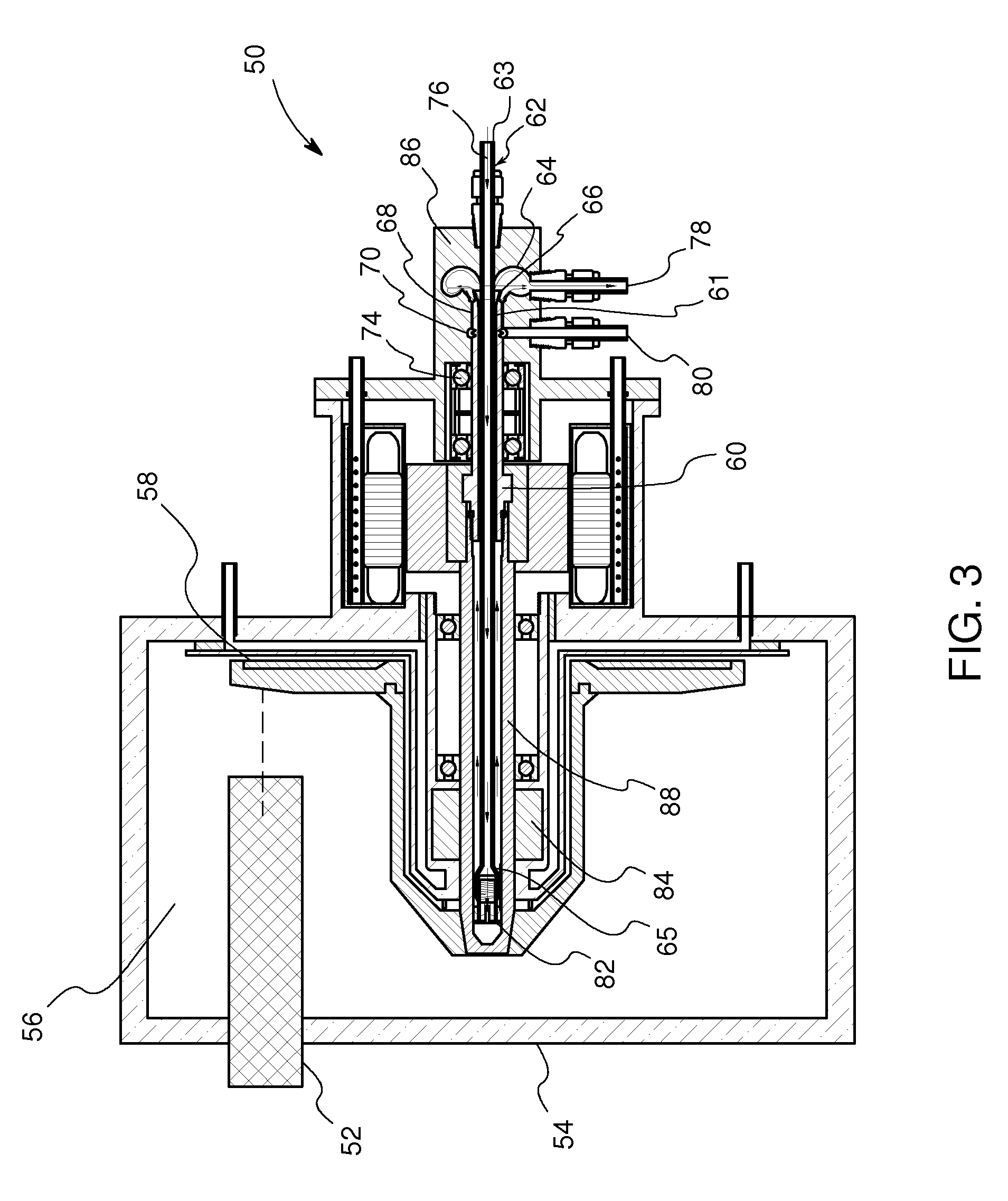
A rotating union for an X-ray target is provided. The rotating union for the X-ray target comprises a housing, a coolant-slinging device comprising a rotating shaft having an inner diameter and an outer diameter, a proximal end and a distal end, and a bore therein, one or more slingers coupled to a proximal end of the rotating shaft; a drain annulus coupled to the one or more slingers, wherein the one or more slingers are configured to direct a coolant to the drain annulus and the drain annulus is configured to direct the coolant through a primary coolant outlet; and a stationary tube having a first end and a second end, wherein at least a portion of the stationary tube is disposed within the bore of the rotating shaft.

Description

BACKGROUND[0001]Embodiments of the present invention relate generally to a rotating union for transferring fluids from a stationary supply to a rotating component. More particularly, the embodiments of the present invention relate to a rotating union for preventing leakage of fluid between a rotating component and a stationary supply in an X-ray tube based imaging system.[0002]X-ray tube based imaging systems, such as computed tomography (CT) imaging systems as well as non-destructive testing systems, employ X-ray sources located on a gantry. Typically these x-ray tubes are anode based x-ray tubes. These anode X-ray tubes typically require high voltage to generate X-rays. Unfortunately these anode X-ray tubes tend to get heated while generating the X-rays. Currently, X-ray tubes employing a rotating shaft protruding out of a vacuum vessel may use a Ferro-fluidic seal to separate vacuum from the atmosphere. The liquid coolant may be directed through the rotating shaft to cool the X-r...

Claims


Application Information

Patent Timeline
Patent Type & Authority Patents(United States)
IPC IPC(8): H01J35/10
CPCH01J35/101H01J35/106H01J2235/1006H01J2235/127H01J2235/1208H01J2235/1266H01J2235/1204H01J35/1017
Inventor SMITH, WALTER JOHNROBINSON, VANCE SCOTTGADRE, ANIRUDDHA DATTATRAYAFRONTERA, MARK ALAN
Owner GENERAL ELECTRIC CO
Learn More