Timing analysis method and apparatus for enhancing accuracy of timing analysis and improving work efficiency thereof

a timing analysis and work efficiency technology, applied in the field of timing analysis methods and apparatuses, can solve the problems of long processing time, inability the situation is reaching the point where it is no longer possible to finish timing analysis in a practical time, so as to improve the work efficiency of timing analysis and enhance the accuracy of timing analysis

Inactive Publication Date: 2011-08-16
FUJITSU LTD
View PDF10 Cites 5 Cited by
  • Summary
  • Abstract
  • Description
  • Claims
  • Application Information

AI Technical Summary

Benefits of technology

[0015]An object of the present invention is to provide a timing analysis method and apparatus that can enhance the accuracy of timing analysis while, at the same time, improving work efficiency for the timing analysis.

Problems solved by technology

Techniques that perform timing analysis based on simulation using the industry standard SPICE have long been known in the art, but such techniques require a very long processing time to finish and, with the ever increasing scale of circuit integration, the situation is reaching the point where it is no longer possible to finish timing analysis in a practical time.
However, in the case of LSI circuits for which feature sizes are decreasing and the packing density increasing year by year, it is not possible, even with the above technique, to provide the necessary accuracy for paths, such as a clock path, that require high accuracy.
However, in the above-described prior art timing analysis methods for large-scale integrated circuits, the simulation conditions for the extracted (corrected) circuit differed considerably from the actual circuit operation, giving rise to the problem of poor accuracy.
Furthermore, the scale of the extracted circuit tended to become large in order to increase the accuracy, and it took considerable time to complete one SPICE simulation.
Further, since the simulation conditions such as simulation patterns had to be set manually, the whole task was very laborious.

Method used


Image

  • Timing analysis method and apparatus for enhancing accuracy of timing analysis and improving work efficiency thereof
  • Timing analysis method and apparatus for enhancing accuracy of timing analysis and improving work efficiency thereof
  • Timing analysis method and apparatus for enhancing accuracy of timing analysis and improving work efficiency thereof

Examples


Embodiment Construction

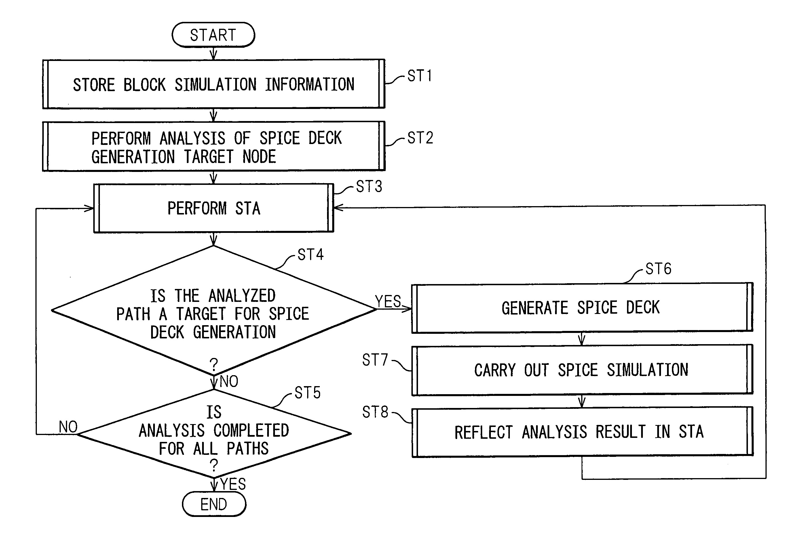
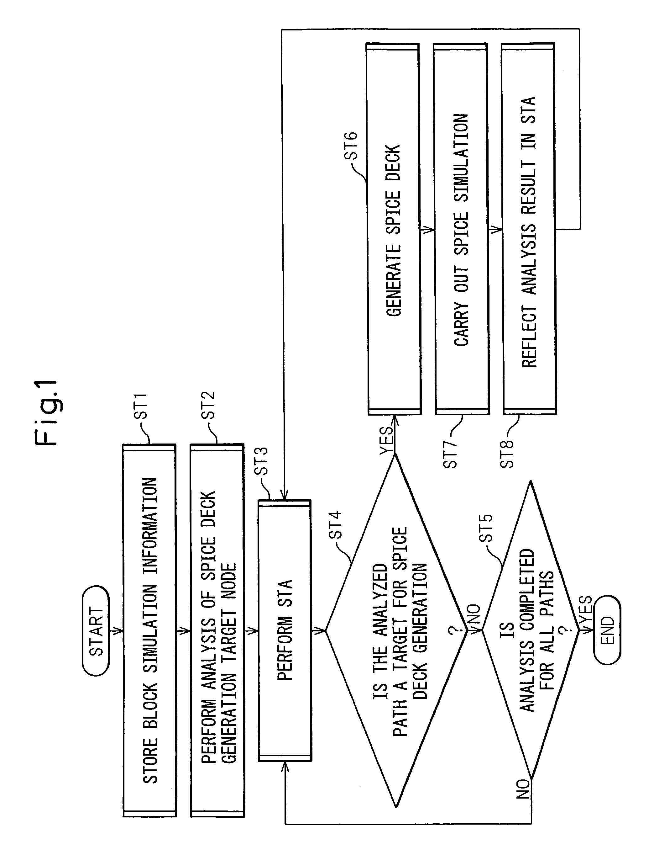
[0050]Before describing in detail the preferred embodiments of the timing analysis method and apparatus according to the present invention, the principles of the present invention will be described first. The invention aims to improve the accuracy of the circuit partitioning technique by the following procedure.

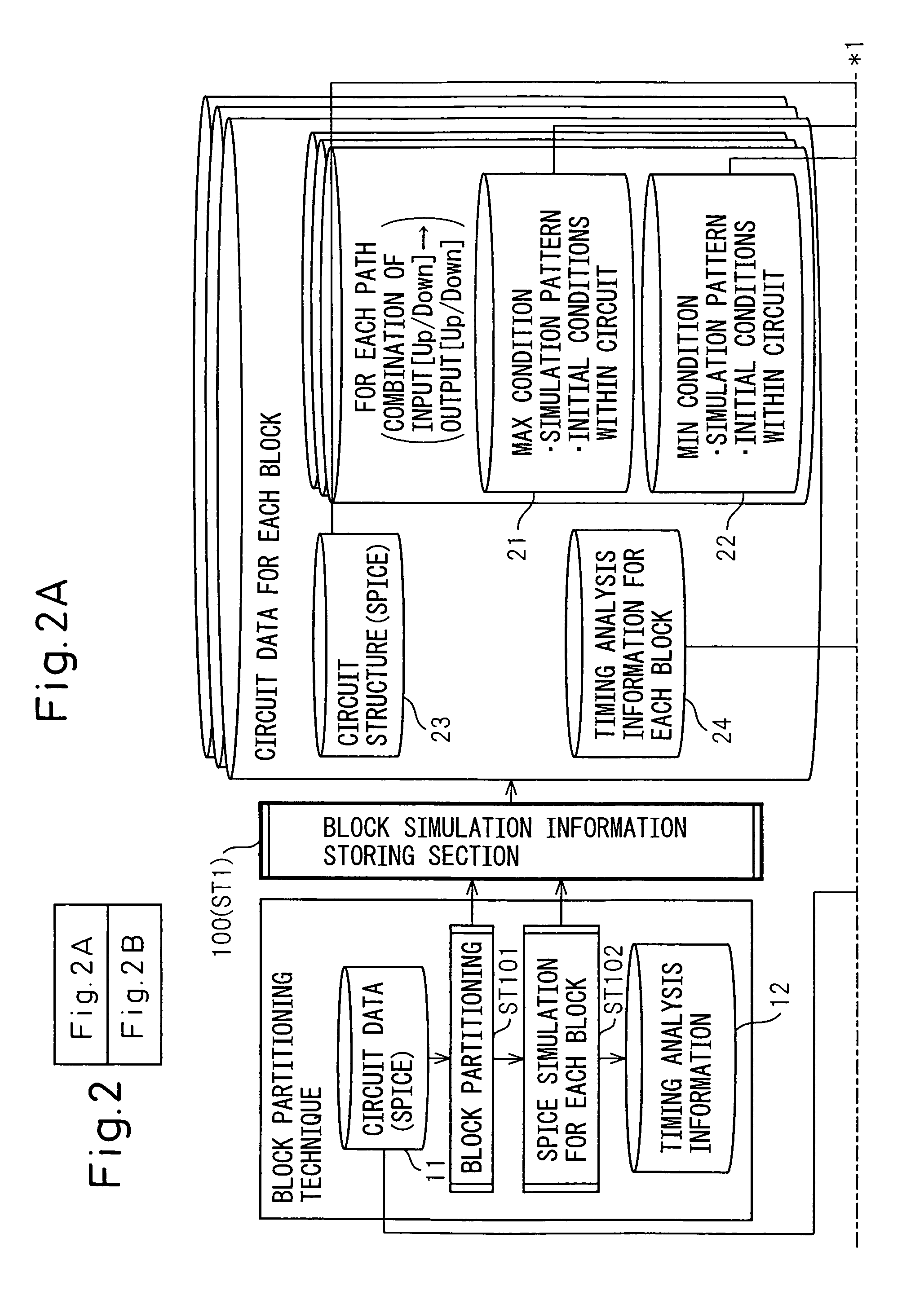
[0051](1) First, block simulation information (only MIN / MAX critical conditions) such as simulation patterns are stored when performing circuit analysis for each block.

[0052](2) Next, a path that need high-accuracy analysis is identified.

[0053](3) Further, for the path that need high-accuracy analysis, a SPICE deck interconnecting the partition blocks is generated by using the result of STA (Static Timing Analysis) and the SPICE simulation conditions for each block, and SPICE simulation is performed. Here, the SPICE deck is a SPICE netlist to be used in the SPICE simulation, and refers to a SPICE netlist in which other simulation conditions are set.

[0054](4) Then, the result ...


PUM


Abstract

A timing analysis apparatus has a block simulation information storing section, a SPICE deck generating section, and a feedback-based static timing analyzing section. The block simulation information storing section stores simulation information for each block when performing circuit analysis by partitioning a circuit into blocks, the SPICE deck generating section generates a SPICE deck by interconnecting the blocks, for a path that needs analysis, by using a result of static timing analysis and using simulation conditions for the each block. The feedback-based static timing analyzing section causes a result of the simulation performed using the generated SPICE deck to be reflected in the static timing analysis.

Description

CROSS REFERENCE TO RELATED APPLICATION[0001]This application is based upon and claims the benefit of priority from the prior Japanese Patent Application No. 2006-275428, filed on Oct. 6, 2006, the entire contents of which are incorporated herein by reference.BACKGROUND OF THE INVENTION[0002]1. Field of the Invention[0003]The present invention relates to a timing analysis method and apparatus. More particularly, the present invention relates to a timing analysis method and apparatus for large-scale integrated circuits.[0004]2. Description of the Related Art[0005]Recently, extremely accurate timing analysis has been required in designing recent ultra-high-speed LSIs that operate at clock frequencies exceeding several GHz. Techniques that perform timing analysis based on simulation using the industry standard SPICE have long been known in the art, but such techniques require a very long processing time to finish and, with the ever increasing scale of circuit integration, the situation ...

Claims


Application Information

Patent Timeline
Patent Type & Authority Patents(United States)
IPC IPC(8): G06F17/50
CPCG06F17/5031G06F30/3312
Inventor ARAYAMA, MASASHI
Owner FUJITSU LTD
Why Eureka
Try Eureka