
Method for enhancing catalyst selectivity

a selectivity and catalyst technology, applied in the direction of physical/chemical process catalysts, liquid chemical processes, gas-gas reaction processes, etc., can solve the problems of low overall pressure drop of the packed bed, achieve high heat transfer rates, reduce the effect of packing bed pressure drop

Active Publication Date: 2011-08-09
ZEROPOINT CLEAN TECH
View PDF43 Cites 28 Cited by
  • Summary
  • Abstract
  • Description
  • Claims
  • Application Information

AI Technical Summary

Benefits of technology

"The invention is a chemical processing method that allows for efficient conduct of highly exothermic reactions, particularly those dependent on temperature and diffusional resistance. The method uses a heat transfer device with at least two channels in common, which allows for efficient heat transfer. The channels are designed to have small dimensions, which results in a packed bed with low pressure drop. The invention also includes a plate type heat exchanger where one set of channels is used for the process gas and one set for the heat transfer fluid, with a large distance between the plates to allow for satisfactory introduction of catalyst structures and achieve the required catalyst loading. The heat transfer is achieved by maintaining a temperature difference between the heat transfer fluid and process fluid. The invention provides a means for efficient chemical processing with high yields and reduced energy consumption."

Problems solved by technology

The increased voidage of the catalyst bed combined with the low overall height and low gas velocity results in a packed bed with a low overall pressure drop.
As the packing provides a sufficient disturbance to the flow it is not desirable to have flow disturbance structures embedded within the heat transfer plates.

Method used

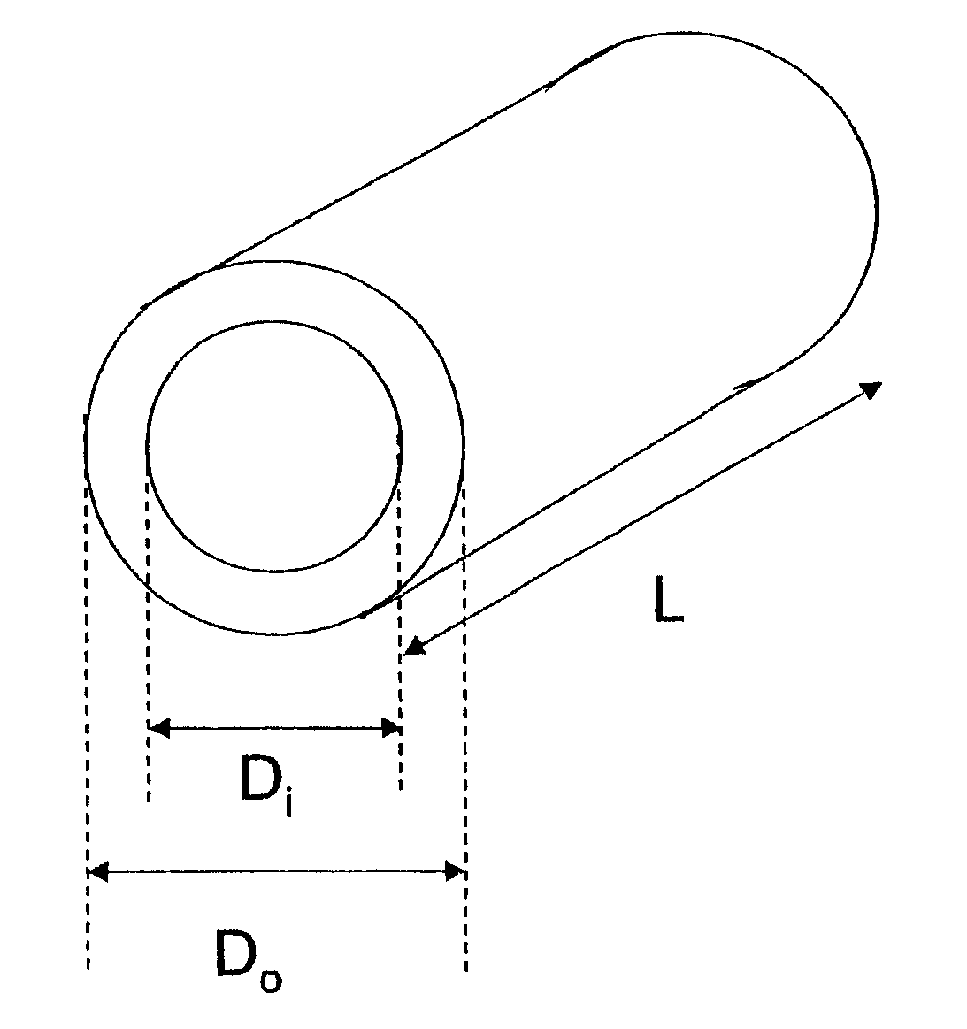
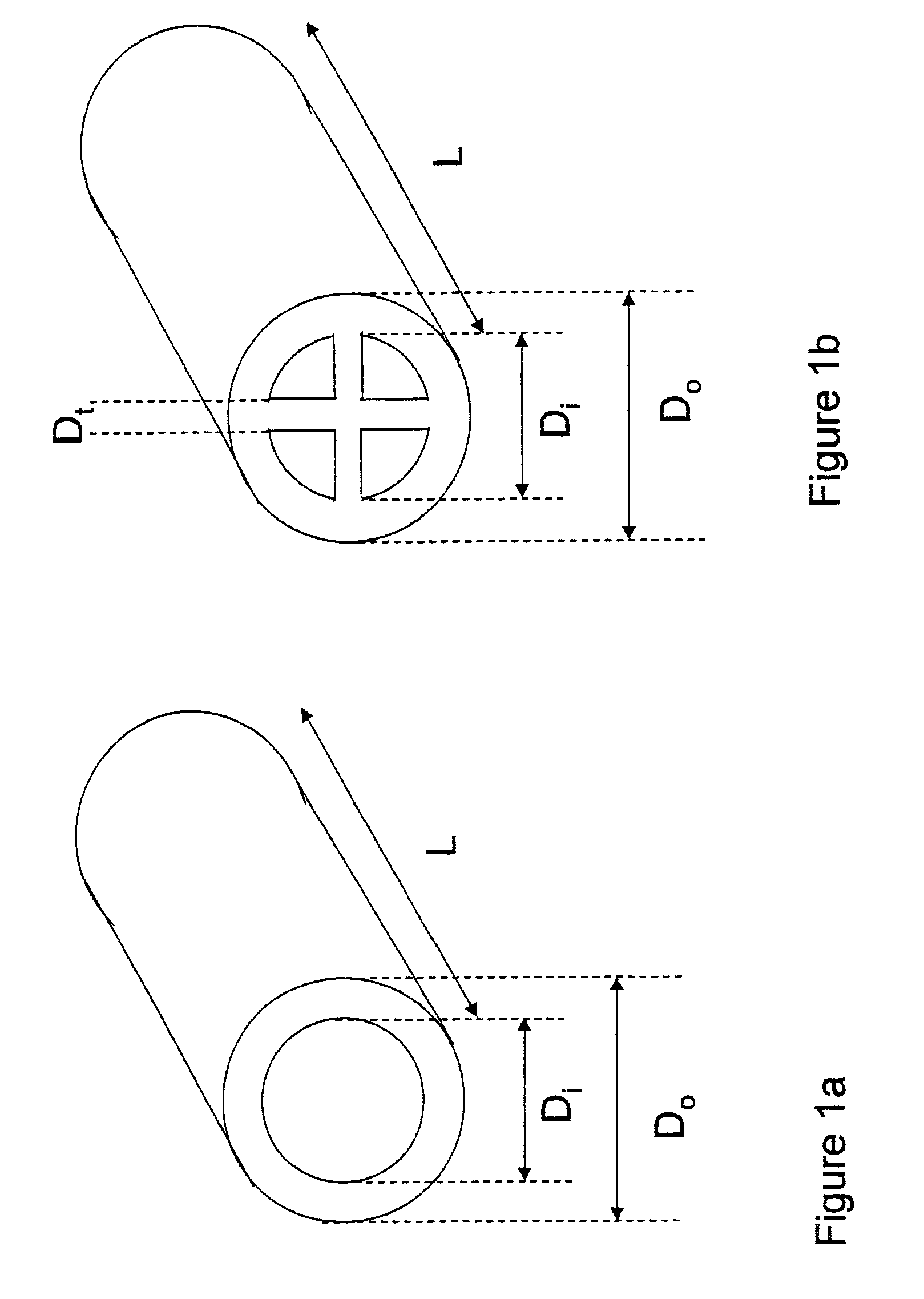
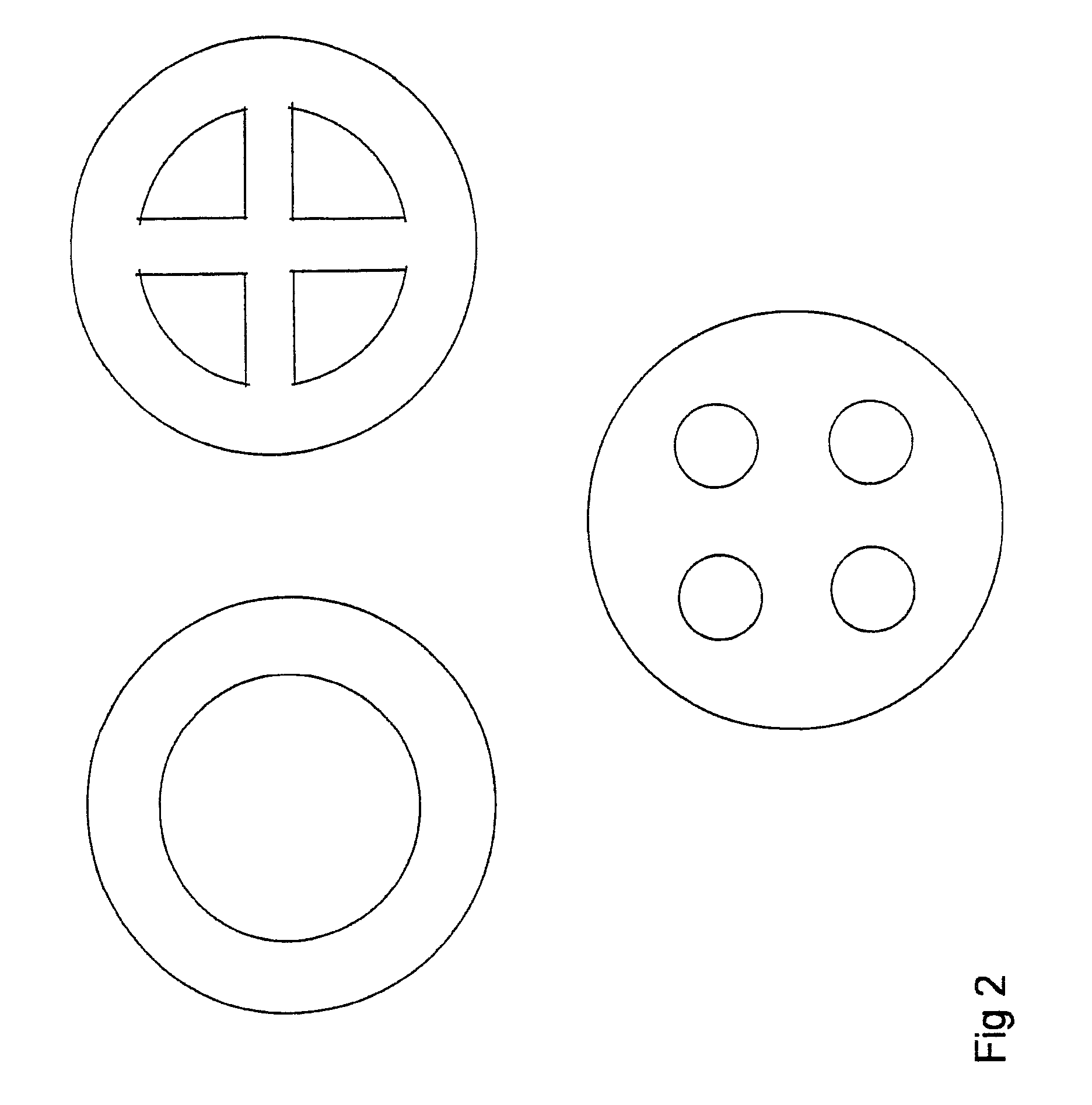

Image

  • Method for enhancing catalyst selectivity
  • Method for enhancing catalyst selectivity
  • Method for enhancing catalyst selectivity

Examples


example 1

[0038]In this example, reaction 3 is the Fischer Tropsch Hydrocarbon Synthesis:

21H2+10COC10H22+10H2O ΔHf=−160 kJ / mol CO  (3)

The heat of reaction in equation 3 equates to a product of a product with an average chain length of 10. Here the reaction is conducted in the reactor illustrated in FIG. 4. Hydrogen and carbon monoxide enter the plate heat exchanger where they contact a suitably impregnated catalyst. The catalyst chosen is a hollow cylinder such that the reactants can readily diffuse into the interior of the particle from both sides. This results in a higher activity and with minimal methane and other byproduct formation. The process conditions are chosen such that the average product composition corresponds to a light middle distillate. The large exotherm causes the process gas temperature to increase. This increase causes a temperature differential between the process gas and the heat transfer fluid. This differential causes energy to flow between the two channels. The heat ...

example 2

[0039]In this example, reaction 4 expresses methanol synthesis from syngas.

2H2+CO⇄CH3OH ΔHf=−90 kJ / mol CO  (4)

Here the reaction is conducted in the reactor illustrated in FIG. 5. Hydrogen and carbon monoxide enter the plate heat exchanger where they contact a suitably impregnated catalyst. The catalyst chosen is a hollow cylinder such that the reactants can readily diffuse into the interior of the particle from both sides. The arrangement results in higher effectiveness factors and better catalyst utilization than a catalyst with the same external dimensions which is not hollow.


PUM

PropertyMeasurementUnit
lengthaaaaaaaaaa
diffusion lengthaaaaaaaaaa
pressure dropaaaaaaaaaa

Abstract

A method allowing the efficient conduction of highly exothermic, catalyst initiated reactions, particularly ones in which the product spectrum is highly dependant upon the temperature at which the process is conducted and to diffusional resistances within the catalyst particle matrix. The process occurs in a heat transfer device which consists of at least two channels which have at least one wall in common. Preferably two distinct sets of flow channels exist in which the process proceeds in one set of channels and heat transfer fluid passes through the second. The area of contact between the two sets of channels is sufficiently large to allow the efficient transfer of heat. These dimensions are controlled through the use of hollow catalyst particles through which the process gas can diffuse through either the inside or outside.

Description

CROSS-REFERENCE TO RELATED APPLICATION[0001]This application claims benefit of U.S. provisional patent application No. 60 / 779,079, filed Mar. 3, 2006, entitled METHOD TO ENHANCE CATALYST SELECTIVITY, and commonly assigned to the assignee of the present application, the disclosure of which is incorporated by reference in its entirety herein.FIELD OF THE INVENTION[0002]The current invention relates to a method of producing catalyst particles which offer minimal resistance to intra particle diffusion and to a chemical reactor for performing reactions utilizing such catalysts.BACKGROUND OF THE INVENTION[0003]Many chemical processes utilize catalytic material to enhance chemical conversion behavior. A catalyst promotes the rate of chemical conversion but does not effect the energy transformations which occur during the reaction. A catalytic chemical reactor therefore must have a facility for energy to flow into or be withdrawn from the chemical process. Often catalytic processes are cond...

Claims


Application Information

Patent Timeline
Patent Type & Authority Patents(United States)
IPC IPC(8): B01J10/00B01J12/00B01J12/02B01J23/02B01J15/00B01J16/00B01J19/00B01J21/04B01J10/02B01J14/00
CPCB01J19/2485B01J19/249B01J19/30B01J35/026B01J37/0201C10G2/33B01J2219/2462B01J2219/2464B01J2219/2465B01J2219/2466B01J2219/2481B01J2219/30223B01J2219/30416C10G2300/703B01J35/55B01J35/50
Inventor LEVESON, PHILIP D.
Owner ZEROPOINT CLEAN TECH
Learn More