Device for automatic indexing of a golf ball

a golf ball and automatic technology, applied in the field of magnetic rotating devices, can solve the problems of tacky ink surface on the pad, and achieve the effect of reducing mechanical wear and tear and reducing the exposure of the ink surfa

Active Publication Date: 2011-08-09
ACUSHNET CO
View PDF37 Cites 8 Cited by
  • Summary
  • Abstract
  • Description
  • Claims
  • Application Information

AI Technical Summary

Benefits of technology

[0012]An object of the present invention is to reduce or eliminate wear and tear on a high speed conveyor line where all movement is automatically generated. The device provides for virtual frictionless rotation to reduce any mechanical wear by having the rotation glide over a ball bearing ring. Multiple station locks, which are located along the conveyor, engage the device and cause the cup portion to rotate (index) therein exposing a new surface for either printing, inspection, or curing. To maintain the cup in position between station locks is the function of the magnets that are disposed in the device. Magnets in the stationary base portion of the device develop a magnetic field with the magnets located in the rotating cup portion. As the devices move along the conveyor, the station locks use an engaging cam section to mesh with an open bridge section of the device to rotate it from a previous position to a new position. At the new position, printing, inspection, or curing procedures are performed, all while the station lock holds the cup device in position. Upon completion of the procedure, the station locks release the device to move along the conveyor line for the next procedure. It is the magnetic forces of the device that hold the rotating cup portion securely to the base portion. Since the device is without any mechanical locking parts, it is the magnetic force of the magnets that firmly holds the rotating portion to the base portion.

Problems solved by technology

The ink is carried on the pad to the target area on the golf ball surface, during which time thinner in the ink further evaporates, causing the exposed ink surface on the pad to become tacky.
While the golf industry needs improvement in automatically orienting, printing and inspecting golf balls produced by high speed production lines, the challenge is in the indexing of the golf ball such that multiple surfaces of the ball are presented sequentially and with extreme precision to the pad printers for the printing of indicia without interrupting the production cycle.

Method used


Image

  • Device for automatic indexing of a golf ball
  • Device for automatic indexing of a golf ball
  • Device for automatic indexing of a golf ball

Examples


Embodiment Construction

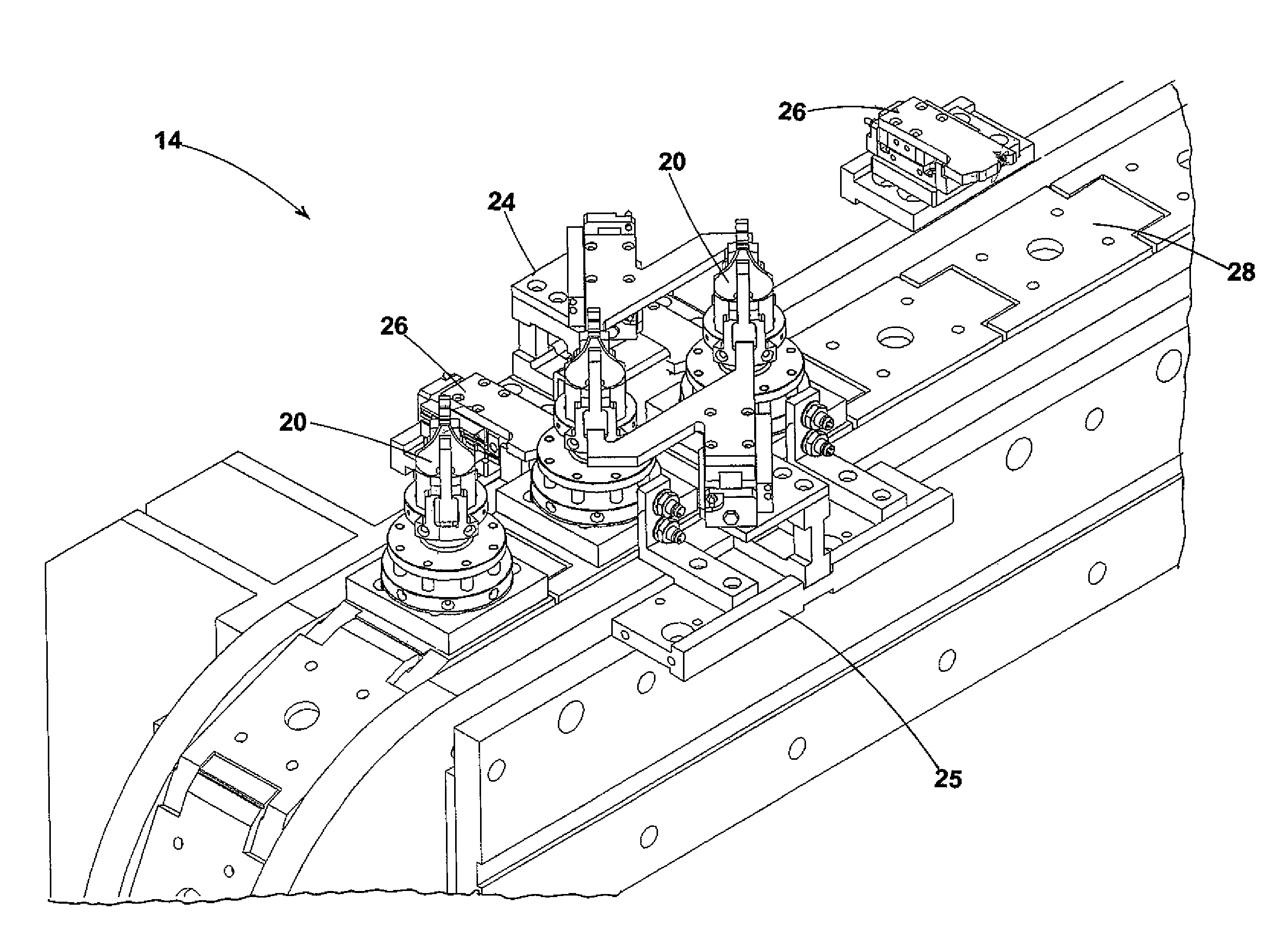
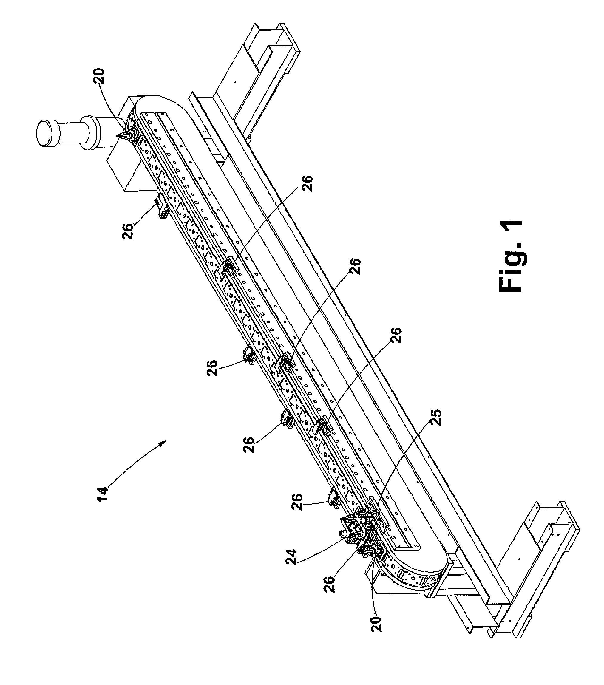
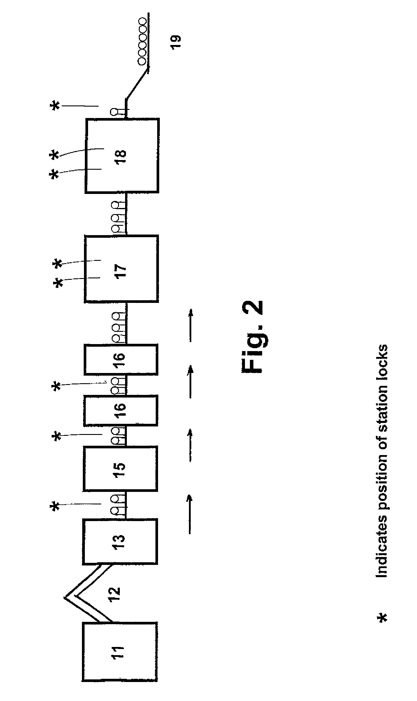
[0024]As illustrated in the accompanying drawings and discussed in detail below, one embodiment of the present invention is directed to a magnetic indexing device 20 that firmly holds a golf ball. Multiple indexing devices 20 are secured to a sled 28 on an endless conveyor 14, as shown on FIGS. 1, 5, and 6. While moving along the conveyor 14, each device 20 is precisely rotated (indexed) such that each and every held ball has the exact same surfaces exposed to articulated pad printers 16 which print indicia and logo thereupon. The balls are also indexed for inspection, curing of the ink, and removal from the device 20.

[0025]As best shown in FIGS. 3 and 4, the device 20 includes two cooperating portions, a stationary base portion 44 and a rotating cup portion 46.

[0026]The stationary base portion 44 includes a square platform 45 that is mechanically connected to the conveyor sled 28 by well known means such as bolting the platform to a sled 28 that is integral with the conveyor 14; a ...


PUM


Abstract

The present invention is directed to a magnetic indexing device that can be connected to a conveyor, the device firmly holding a golf ball in a particular orientation for the purposes of printing of indicia and logo on the ball when device and ball move along the conveyor. The device includes a stationary base portion and a rotating cup portion which are magnetically coupled to each other. Each portion has recesses for housing magnets to create a magnetic field of attraction which firmly locks the two portions together. When rotation of the cup portion to the base portion is required, the rotation is substantially friction-free because of a thrust bearing ring set in the base portion. The cup portion is caused to rotate 45° or 90° upon being biasly urged by station locks located on the conveyor. The cup portion has an open bridge section wherein cam surfaces of the station locks can engage and cause the cup portion to rotate, which is necessary for each new procedure, whether it be inspection of the ball, pad printing of indicia and logo, or curing the printed ink with ultraviolet light.

Description

FIELD OF THE INVENTION[0001]This invention generally relates to a magnetic rotating device used in the indexing of a golf ball for the purpose of printing indicia on multiple surfaces. This invention more particularly relates to a device that magnetically controls the orientation of the golf ball in predetermined positions.BACKGROUND OF THE INVENTION[0002]More than seven hundred million golf balls are produced each year, a significant percentage of which have indicia or logos printed on their outer surface. The indicia typically include any one of the golf ball company, trade name, a number, or an image, such as a corporate or country club logo. The indicia are typically printed on a base-coated surface of the cover of the golf ball, and covered with a top-coating to prevent damage during impact with a golf club. Thus, the indicia must have a perfect appearance since it is often the most distinctive quality of a golf ball.[0003]The golf bail cover typically contains a white or other...

Claims


Application Information

Patent Timeline
Patent Type & Authority Patents(United States)
IPC IPC(8): B25B11/00
CPCB41F17/001B41F17/30Y10T279/23B41P2217/60
Inventor VIEIRA, MICHAEL F.MYDLACK, THOMAS L.MAHER, EDMUND T.MOORE, THOMAS E.
Owner ACUSHNET CO
Why Eureka
Try Eureka