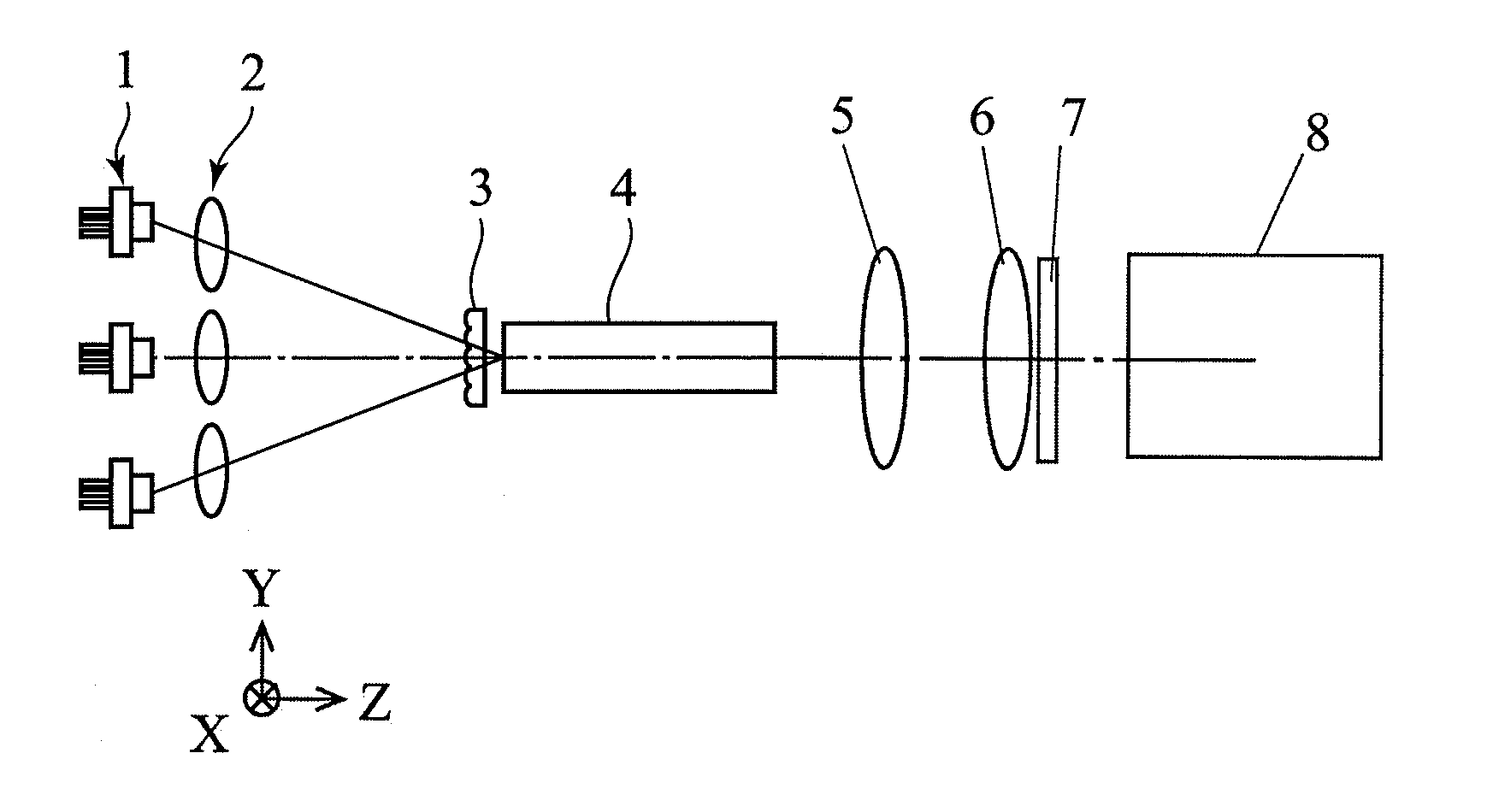
Projection type display device and light source device
a technology of projection type and light source, which is applied in the direction of instruments, semiconductor lasers, optical elements, etc., can solve the problems of invariably increasing focal length, limiting the output obtained by one semiconductor laser, and increasing the aperture diameter of the focusing lens
- Summary
- Abstract
- Description
- Claims
- Application Information
AI Technical Summary
Benefits of technology
Problems solved by technology
Method used
Image
Examples
first embodiment
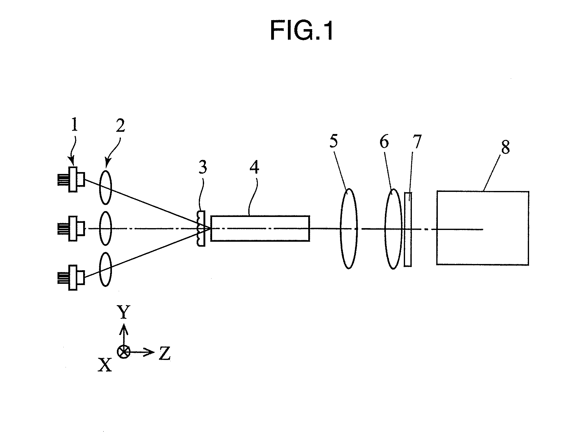
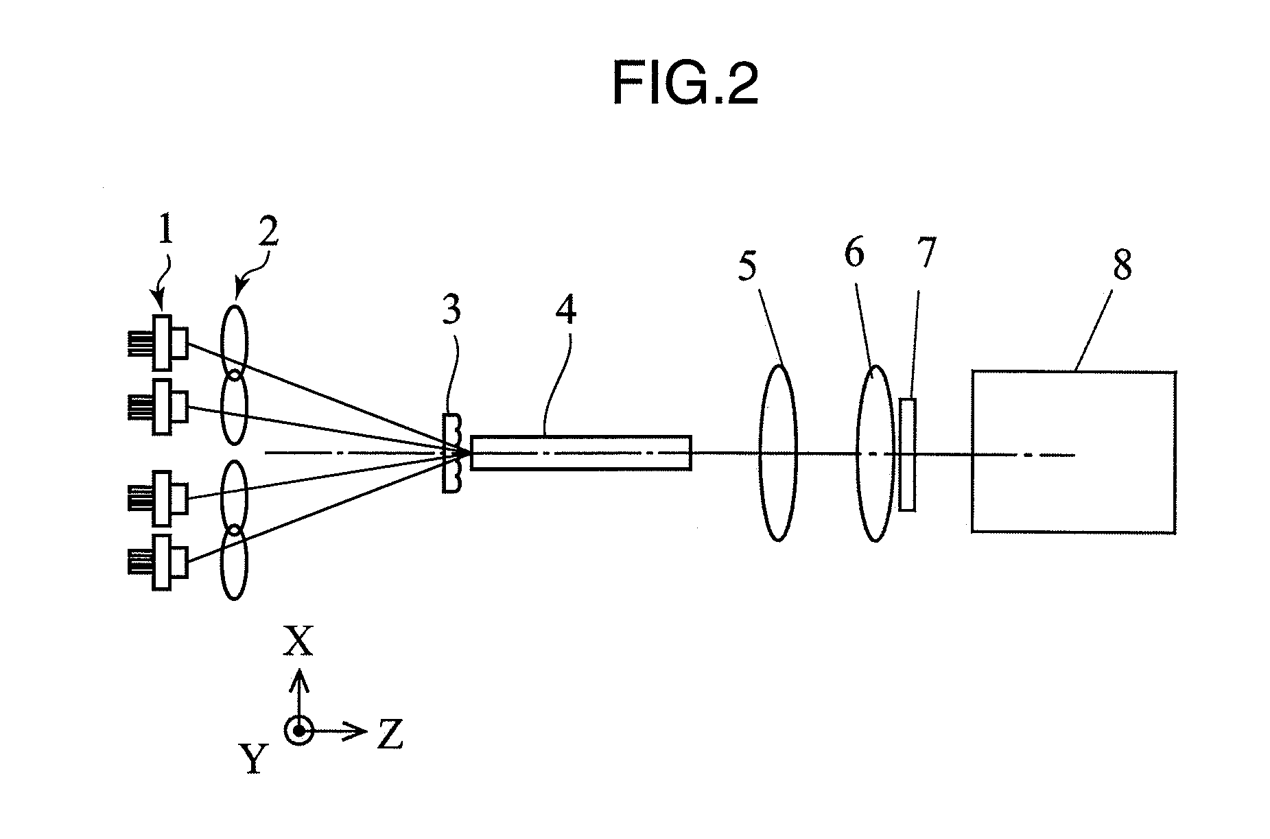
[0038]FIGS. 1 and 2 are views showing a projection type display device according to a first embodiment of the present invention. X-, Y- and Z-axes are defined as shown in FIGS. 1 and 2. FIG. 1 is a YZ side view of the projection type display device according to the first embodiment of the present invention, and FIG. 2 is an XZ side view of the projection type display device according to the first embodiment of the present invention.
[0039]In FIGS. 1 and 2, the projection type display device according to the first embodiment is provided with a laser light source unit 1, a focusing lens unit 2, a lenticular lens 3, a rod integrator 4, a relay lens 5, a field lens 6, a spatial light modulation element 7 and a projection lens 8.
[0040]The laser light source unit 1 is comprised of six semiconductor lasers as described later and emits red or blue laser lights. The focusing lens unit 2 is comprised of six lenses as described later and focuses the laser lights emitted from the laser light sou...
second embodiment
[0059]FIG. 6 is a diagram showing the construction of a projection type display device according to a second embodiment of the present invention. In FIG. 6, the same constituent elements as those in FIGS. 1 and 2 are not described by being identified by the same reference numerals.
[0060]In FIG. 6, the projection type display device according to the second embodiment is provided with a laser light source unit 1, a focusing lens unit 2, a lenticular lens 3, a rod integrator 4, a relay lens 5, a field lens 6, a spatial light modulation element 7, a projection lens 8, a convex lens 9 and a concave lens 10. The convex lens 9 and the concave lens 10 constitute a telephoto type optical system, and a parallel light incident on the convex lens 9 is focused to an incident surface of the rod integrator 4. The operation of the projection type display device according to the second embodiment of the present invention is described below with reference to FIG. 6.
[0061]The light emission regions of...
third embodiment
[0063]FIG. 7 is a diagram showing the construction of a projection type display device according to a third embodiment of the present invention. In FIG. 7, the same constituent elements as those in FIGS. 1 and 2 are not described by being identified by the same reference numerals.
[0064]In FIG. 7, the projection type display device according to the third embodiment is provided with a laser light source unit 1, a focusing lens unit 2, a lenticular lens 3, a rod integrator 4, a relay lens 5, a field lens 6, a spatial light modulation element 7, a projection lens 8, a first convex lens 11 and a second convex lens 12. An interval between the first and second convex lenses is set at about the sum of focal lengths of the respective lenses, and lights focused by the first convex lens 11 are focused to an incident end surface of the rod integrator 4 by the second convex lens 12. The first and second convex lenses 11, 12 constitute a telephoto type optical system, and a lens interval can be m...
PUM
 Abstract
Description
Claims
Application Information
 - R&D
- Intellectual Property
- Life Sciences
- Materials
- Tech Scout
- Unparalleled Data Quality
- Higher Quality Content
- 60% Fewer Hallucinations
Browse by: Latest US Patents, China's latest patents, Technical Efficacy Thesaurus, Application Domain, Technology Topic, Popular Technical Reports.
© 2025 PatSnap. All rights reserved.Legal|Privacy policy|Modern Slavery Act Transparency Statement|Sitemap|About US| Contact US: help@patsnap.com


