
Epoxy resin composition for optical semiconductor element encapsulation and optical semiconductor device using the same

a technology of optical semiconductor elements and epoxy resin, which is applied in the direction of semiconductor devices, solid-state devices, basic electric elements, etc., can solve the problems of poor workability, cost rise, and package cracking, and achieve excellent not only cracking resistance, excellent solder reflow resistance, and excellent cracking resistan

Active Publication Date: 2011-07-26
NITTO DENKO CORP
View PDF8 Cites 3 Cited by
  • Summary
  • Abstract
  • Description
  • Claims
  • Application Information

AI Technical Summary

Benefits of technology

[0005]Under these circumstances, the present invention has been made and an object of the present invention is to provide an epoxy resin composition for optical semiconductor element encapsulation, which has of course good transparency and is excellent in cracking resistance during solder reflow and at the same time, excellent in the temperature cycle test reliability, and an optical semiconductor device using the same and having high reliability.
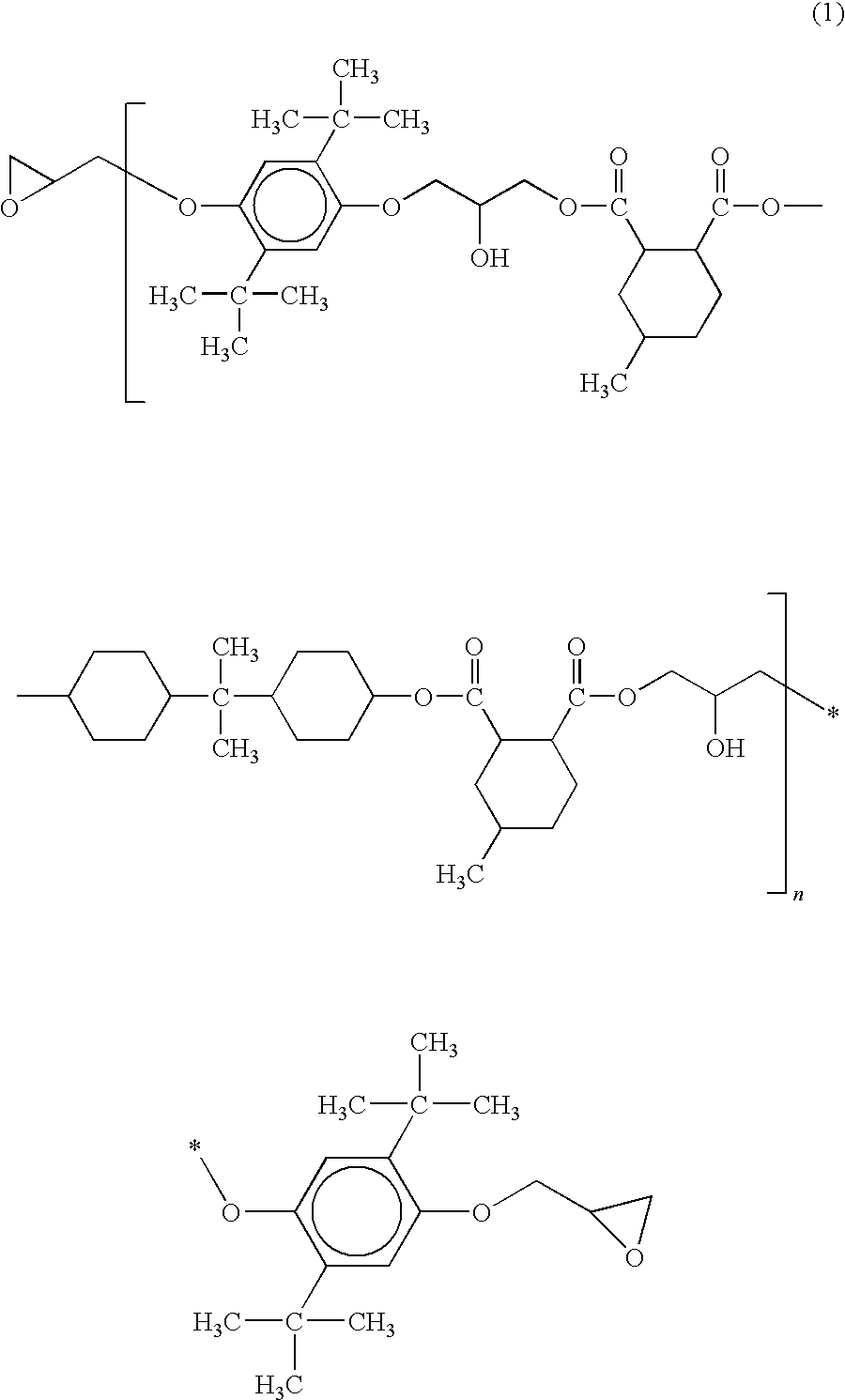
[0025]The present inventors have made a series of studies to obtain an epoxy resin composition for optical semiconductor element encapsulation, which is excellent in cracking resistance during solder reflow. As a result, it has been found that when an epoxy resin represented by structural formula (1) (component (A)) and an epoxy resin other than that (component (B)) are combined in a specific ratio, the high-temperature elastic modulus at a solder reflow temperature (rubbery region) becomes low compared with conventional epoxy resins and the stress generated due to vaporization and expansion on performing reflow can be relieved, thereby ensuring that generation of cracking is of course suppressed to provide excellent solder reflow resistance and moreover, the glass transition temperature becomes high to also allow for enhancement in terms of temperature cycle test reliability. The present invention has been accomplished based on this finding.
[0026]In this way, the present invention relates to an epoxy resin composition for optical semiconductor element encapsulation, including an epoxy resin represented by structural formula (1) (component (A)) and an epoxy resin other than that (component (B)) in a specific mixing ratio. Accordingly, the epoxy resin composition for optical semiconductor element encapsulation of the present invention is excellent not only in the cracking resistance during solder reflow but also in the temperature cycle test reliability owing to its high glass transition temperature and becomes a useful encapsulating material and in turn, an optical semiconductor device with high reliability can be obtained.

Problems solved by technology

In the case where this stress exceeds the package strength, cracking occurs in the package.
However, there is involved a cost rise due to moisture-proof packing, bad workability due to packing and unpacking, or a large burden due to the cost of heating and drying.
The approach in general for solving the problem of cracking of the encapsulating resin due to water vapor includes a method of incorporating a large amount of a high-strength structural material such as filler into the encapsulating resin, but in the usage for an optical semiconductor, from the standpoint of transparency, it is difficult to use the technique of incorporating a large amount of a high-strength structural material such as filler.
However, since the glass transition temperature (Tg) of the epoxy resin composition is high and the elastic modulus during solder reflow rises, the stress due to vaporization and expansion when performing reflow cannot be relieved and generation of cracking occurs.
However, this method has a problem in that the temperature cycle reliability is significantly low and the product reliability is not satisfied.

Method used


Image

  • Epoxy resin composition for optical semiconductor element encapsulation and optical semiconductor device using the same
  • Epoxy resin composition for optical semiconductor element encapsulation and optical semiconductor device using the same
  • Epoxy resin composition for optical semiconductor element encapsulation and optical semiconductor device using the same

Examples


example

[0071]Examples and Comparative Examples are described together below, but the present invention is not limited to these Examples.

[0072]Examples in accordance with a first embodiment of the present invention and Comparative Examples are described below.

[0073]In advance of Examples and Comparative Examples, the components shown below were prepared.

[0074]Epoxy Resin a: Epoxy resin represented by structural formula (1) (in formula (1), n=1; epoxy equivalent: 540; ZX-1718-3 produced by Tohto Kasei Co., Ltd.)

[0075]Epoxy Resin b: Bisphenol A-type epoxy resin (epoxy equivalent: 185, liquid form)

[0076]Epoxy Resin c: Bisphenol F-type epoxy resin (epoxy equivalent: 170, liquid form)

[0077]Epoxy Resin d: Biphenyl-type epoxy resin represented by the following structural formula (b) (epoxy equivalent: 193, melting point: 105° C.):

[0078]

[0079]Epoxy Resin e: 3,4-Epoxycyclohexenylmethyl-3′,4′-epoxycyclohexene carboxylate (epoxy equivalent: 134)

[0080]Curing Agent: Hexahydrophthalic anhydride

[0081]Curi...


PUM

PropertyMeasurementUnit
glass transition temperatureaaaaaaaaaa
temperatureaaaaaaaaaa
softening pointaaaaaaaaaa

Abstract

The present invention relates to an epoxy resin composition for optical semiconductor element encapsulation, the epoxy resin composition including following components (A) to (C):(A) an epoxy resin represented by the following structural formula (1):in which n is a positive number,(B) an epoxy resin except for the epoxy resin represented by the structural formula (1), and(C) a curing agent.

Description

FIELD OF THE INVENTION[0001]The present invention relates to an epoxy resin composition for optical semiconductor element encapsulation, which is used for encapsulation of various optical semiconductor elements, and relates to an optical semiconductor device obtained by encapsulating an optical semiconductor element with the epoxy resin composition.BACKGROUND OF THE INVENTION[0002]Conventionally, an epoxy resin composition has been used from the standpoint that the encapsulating material for an optical semiconductor element such as light-receiving element and light-emitting element must be excellent in transparency, moisture resistance and heat resistance. The epoxy resin is, for example, transfer-molded in a forming mold having placed therein an optical semiconductor element, whereby the optical semiconductor element is formed as a package to obtain an optical semiconductor device (see, for example, JP-A-2006-93277).[0003]Similarly to a semiconductor package other than an optical s...

Claims


Application Information

Patent Timeline
Patent Type & Authority Patents(United States)
IPC IPC(8): H01L23/28H01L23/29
CPCC08G59/226C08L63/00H01L31/0203H01L33/56C08L2666/22
Inventor OTA, SHINYAFUKE, KAZUHIROGOTO, CHISATOITO, HISATAKATANIGUCHI, TAKASHIYOSHIDA, KAZUHIKOGUNJI, MASAOTAKUWA, SEIGOU
Owner NITTO DENKO CORP
Learn More