Resonator comprised of a bent conductor line with slits therein and a filter formed therefrom
a resonator and conductor material technology, applied in the direction of resonators, superconductors/hyperconductors, waveguides, etc., can solve the problems of loss in the resonator, conductive property of the conductor material may be destroyed, current concentration on the edge poses a problem, etc., and achieves low loss property and high-power handling
- Summary
- Abstract
- Description
- Claims
- Application Information
AI Technical Summary
Benefits of technology
Problems solved by technology
Method used
Image
Examples
first embodiment
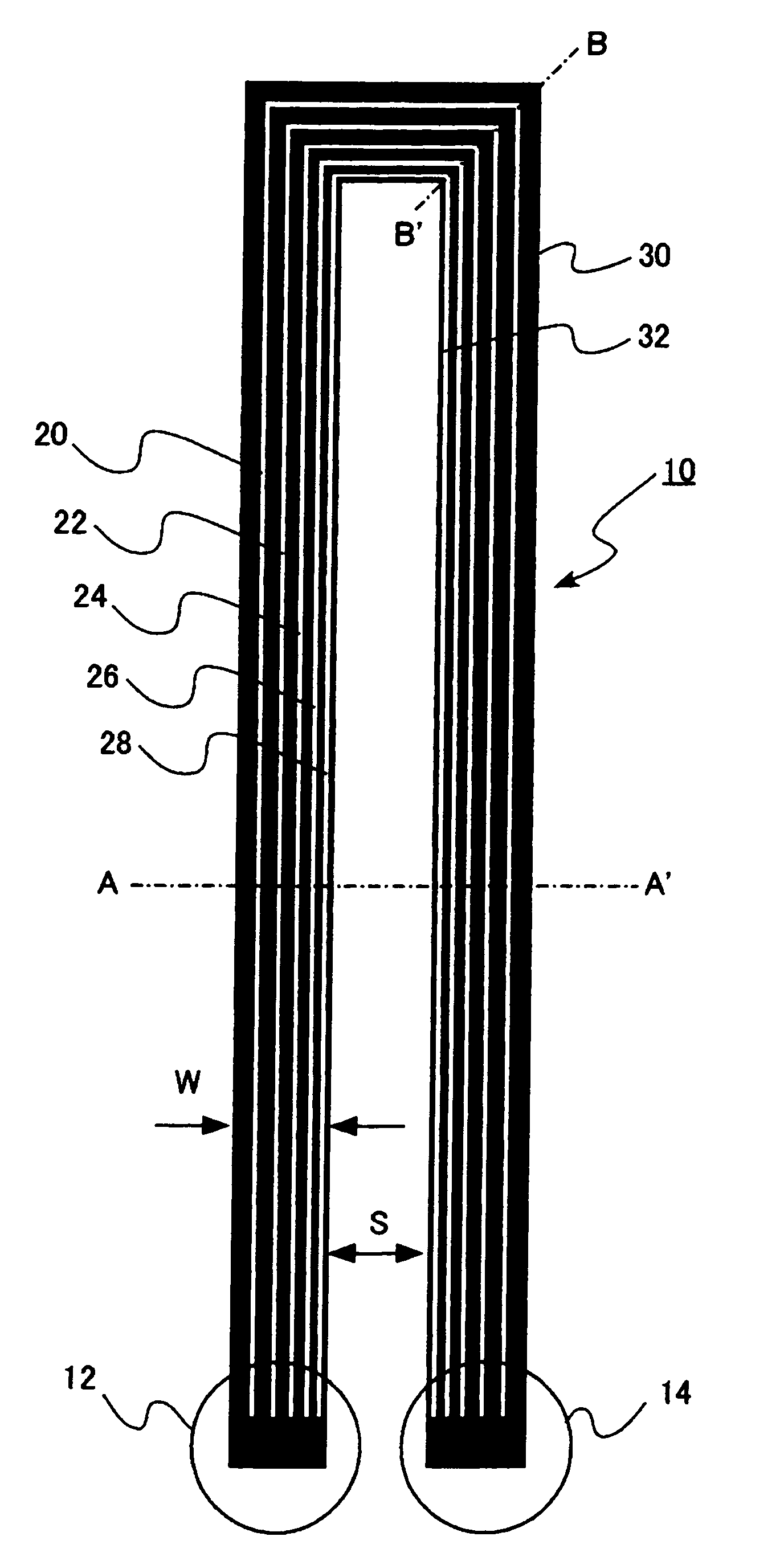
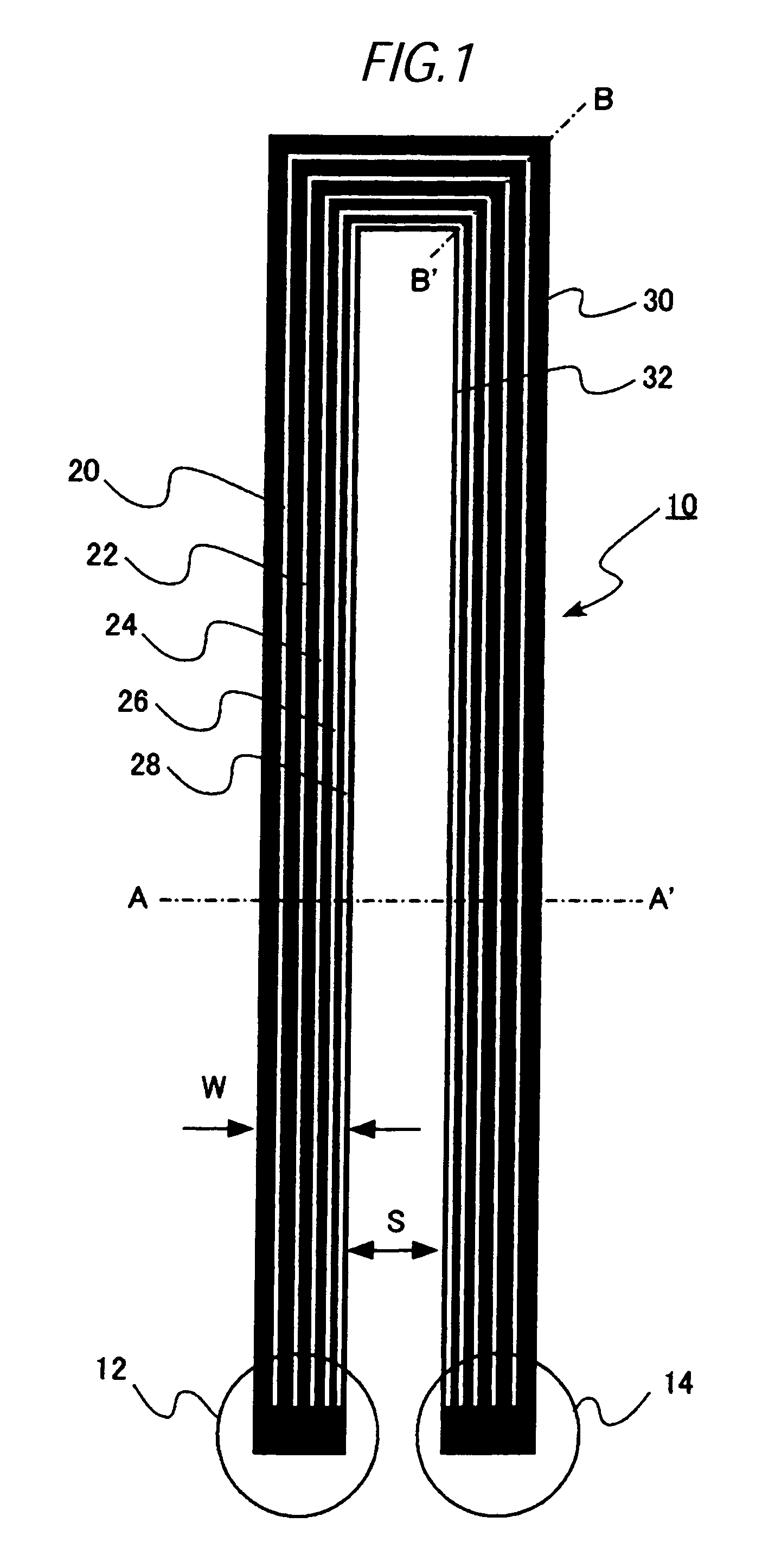
[0054]A resonator according to a first embodiment of the present invention consists of a transmission line with a conductor line having a bent portion. A microstrip line, in which a plurality of slits are formed in the conductor line along the extending direction thereof, and in which intervals of the slits become narrower toward the inner-side of the bent portion, is used as the transmission line.
[0055]As mentioned above, the slits, which are narrower toward the inner-side of the bent portion, are provided in the transmission line, so that a current concentration on inner-side edges of the bent portion can be prevented and a high power handling and a low power loss of the resonator can be attained.
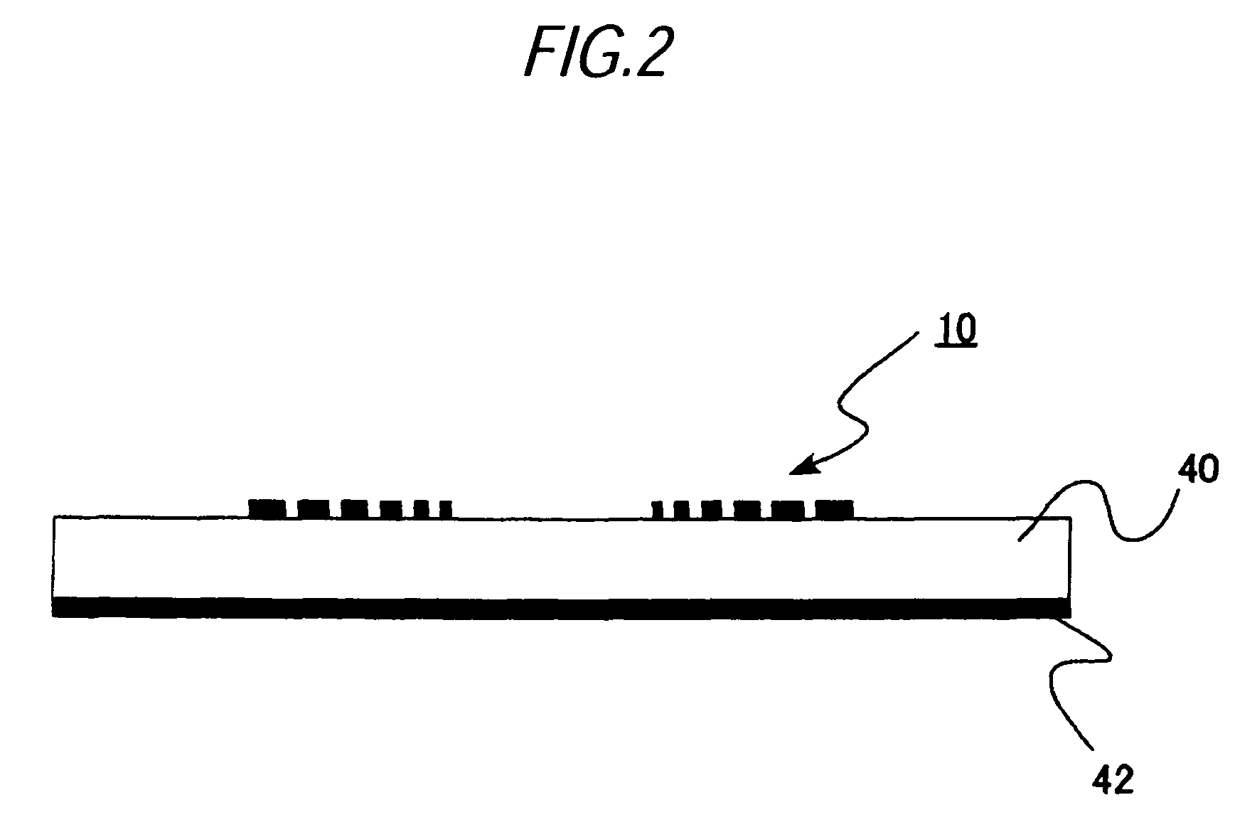
[0056]FIG. 1 is a plan view showing a conductor line pattern of the resonator of the present embodiment. In the present embodiment, a microstrip line is used as the transmission line constituting the resonator. The drawing shows a top view of a substrate of a microstrip line, as viewed fr...
second embodiment
[0070]A resonator according to a second embodiment of the present invention is analogous to the resonator according to the first embodiment except the following features, and hence its explanations are omitted. The slit length ranges from 45 degrees to 90 degrees of an electrical length at a resonance frequency of the resonator. Essentially-center portions of the slits achieved in the lengthwise direction thereof are located in the center of the bent portion.
[0071]An unwanted resonance mode can be avoided by reducing the slit length, while attaining the high power handling and the low conductor loss by relaxing a current concentration on a bent portion.
[0072]FIG. 8 is a plan view showing a conductor line pattern of the resonator of the present embodiment. As in the first embodiment, a microstrip line is used. The drawing is a view of a substrate of a microstrip line acquired when viewed from the direction of an upper surface thereof, and black-painted areas constitute the conductor ...
third embodiment
[0090]A filter according to a third embodiment of the present invention corresponds to a filter built from, for instance, a single or a plurality of resonators described in connection with the first and second embodiments.
[0091]FIG. 28 is a plan view showing a conductor line pattern in the filter of the present embodiment. In the conductor line, six resonators 60, 62, 64, 66, 68, and 70 are arranged in series, to thus constitute a six-stage Chebyshev filter, wherein the resonators have the same shape as that of the resonator shown in FIG. 8. At both ends of the resonators, L-shaped conductor lines are arranged and are extended toward ends of a substrate, to thus constitute input and output feeders 72 and 74.
[0092]As mentioned above, the filter is built by use of low-loss, high-power-handling resonators, whereby a low-loss, high-power-handling filter can be implemented. Although the six-stage Chebyshev filter is described as an example, the present invention is not limited thereto. S...
PUM
| Property | Measurement | Unit |
|---|---|---|
| slit width | aaaaa | aaaaa |
| resonance frequency | aaaaa | aaaaa |
| resonance frequency | aaaaa | aaaaa |
Abstract
Description
Claims
Application Information
 - R&D
- Intellectual Property
- Life Sciences
- Materials
- Tech Scout
- Unparalleled Data Quality
- Higher Quality Content
- 60% Fewer Hallucinations
Browse by: Latest US Patents, China's latest patents, Technical Efficacy Thesaurus, Application Domain, Technology Topic, Popular Technical Reports.
© 2025 PatSnap. All rights reserved.Legal|Privacy policy|Modern Slavery Act Transparency Statement|Sitemap|About US| Contact US: help@patsnap.com


