
Optical emission collection and detection device and method

Inactive Publication Date: 2011-07-19
FLIR DETECTION
View PDF15 Cites 10 Cited by
  • Summary
  • Abstract
  • Description
  • Claims
  • Application Information

AI Technical Summary

Benefits of technology

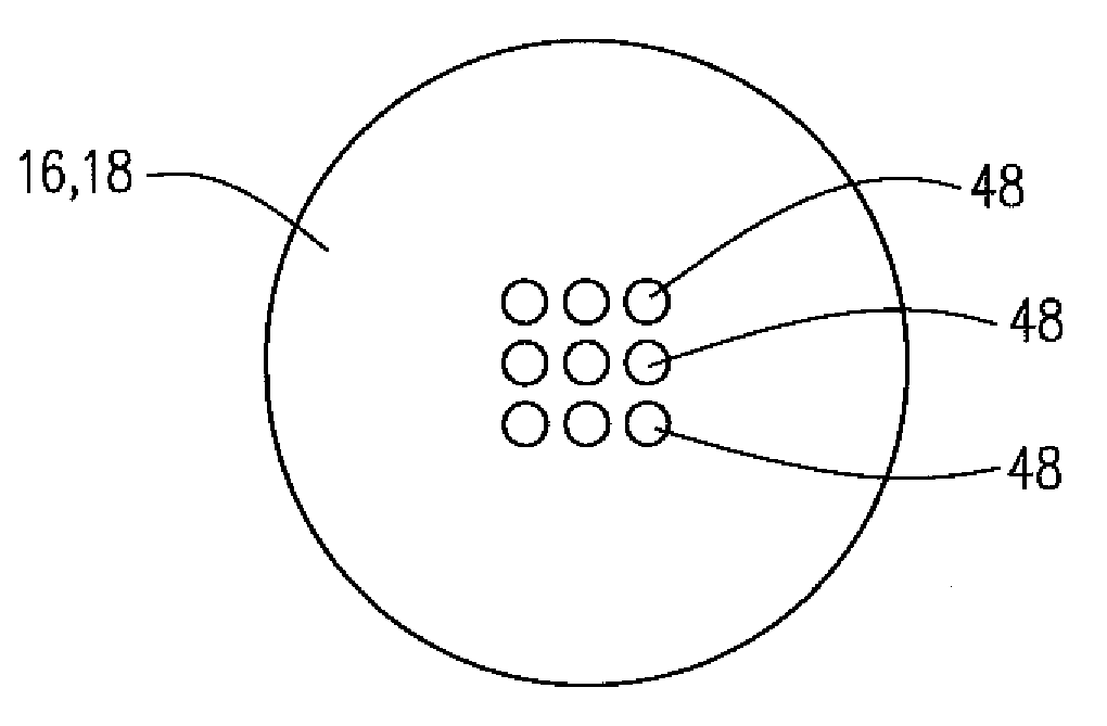
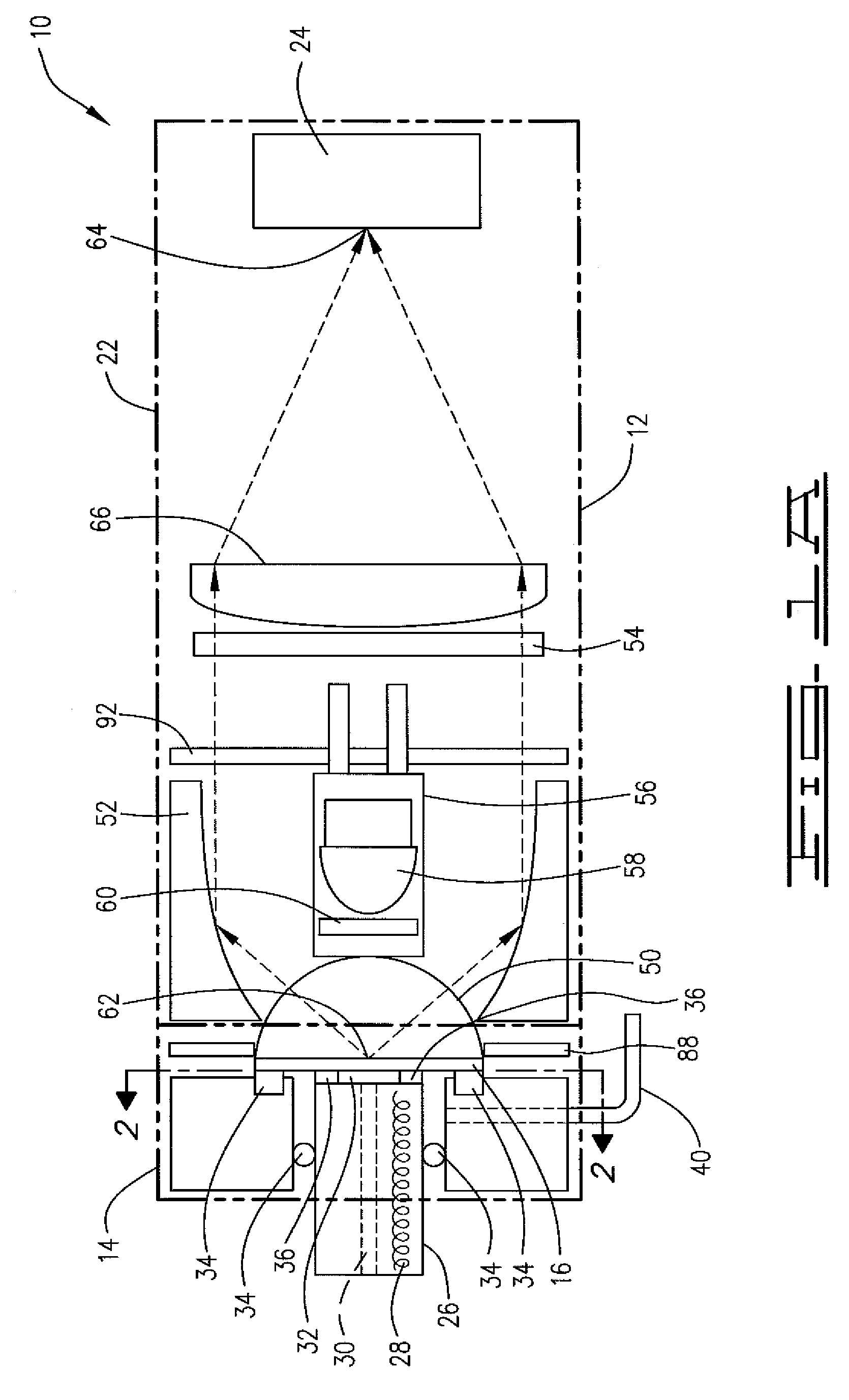
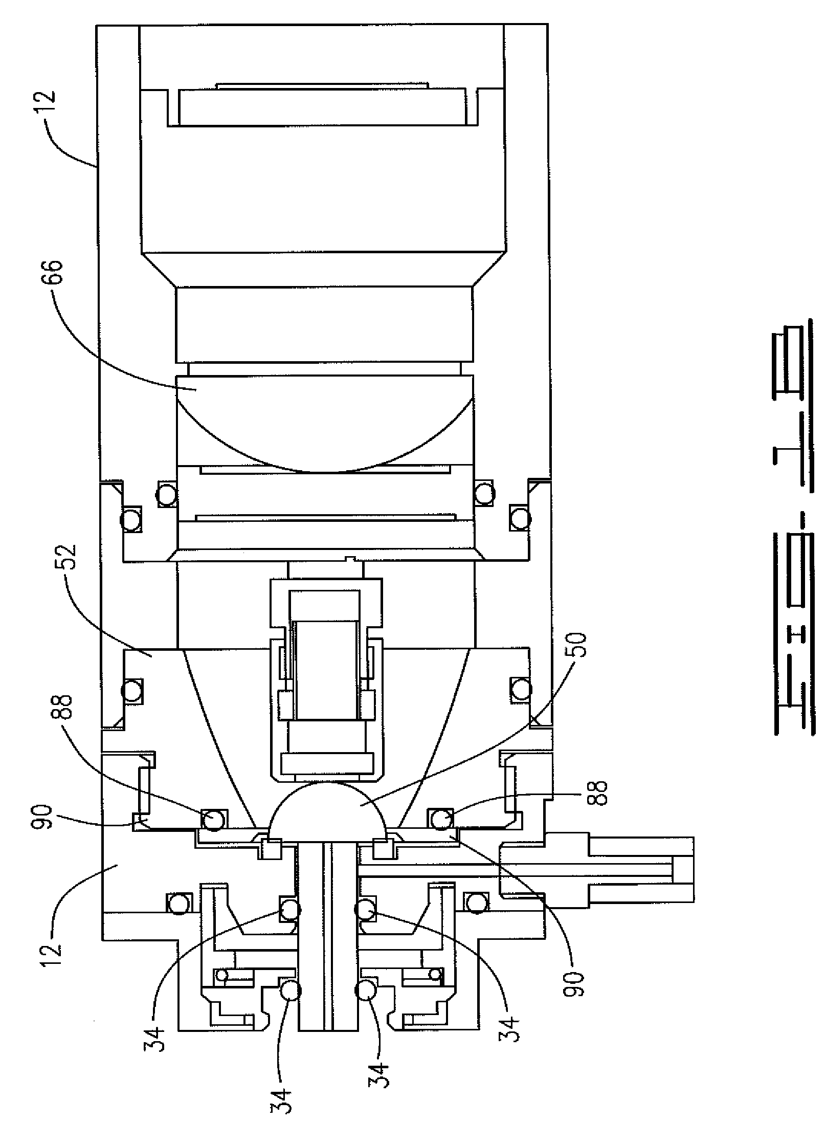
[0028]Another embodiment of this invention is a fluorescence collection optical system. The fluorescence collection optical system has an ellipsoidal mirror. An emission source is optically positioned at the first foci of the ellipsoidal mirror. The emission source preferably comprises a surface plasmon coupled emission slide and fluorescence material coated on a reacting side of the surface plasmon coupled emission slide. The surface plasmon coupled emission slide is preferably a multilayered slide that is capable of redistributing the emission from the fluorescence material. The surface plasmon coupled emission slide has multiple metallic and dielectric thin layers coated on a transparent substrate. Preferably, the thickness and the refractive index of the dielectric layer specify the surface plasmon coupled emission angle. The surface plasmon coupled emission slide preferably has a reacting side and a mounting side. A reactive coating is positioned on the reacting side. The reactive coating on the reacting side of the surface plasmon coupled emission slide is comprised of fluorescence material such as CWIC or AFP. There is an emission source deposited on the reactive coating. Preferably, the emission source is a fluorescence material such as CWIC or AFP. The mounting side of the slide is attached to the flat side of a half-ball prism lens with index matching material. Preferably, the index matching material is an optical index matching fluid. The emission source has an analyte transport fluid flowing across and contacting the reacting side of the surface plasmon coupled emission slide. The emission source produces an excited emission light wave, such as the fluorescence, when stimulated. The excited emission light redistributed by the surface plasmon couple emission mechanism is hence allowed to penetrate through the substrate of the surface plasmon coupled emission slide and the index matched half-ball prism lens. The presence of the prism lens allows the excited emission light to exit the prism lens without being trapped by the total internal reflection.
[0029]In the fluorescence collection optical system, the excitation assembly contains an excitation filter and a light source. The excitation assembly is affixed to the back of the half-ball prism lens. The excitation filter is positioned between the light source and the half-ball prism lens. The light source provides the stimulus to excite the emission source through the excitation filter and is loosely focused by the half-ball prism lens. A spatial filter is inserted in the optical path to filter any light wave traveling within the ellipsoidal mirror. The spatial filter limits the angle of the reflected emission of the excited light wave, and blocks the undesired light such as the scattered excitation and ambient light. The spatial filter is configured to allow the excited emission light wave to pass through with specified transmission angles ranging from 55 degrees to about 85 degrees. The excitation assembly affixed to the back of the half-ball prism lens blocks any light wave with a transmission angle of less than 55 degrees. An emission detection sensor is positioned at the second foci of the ellipsoidal mirror. The emission detection sensor is preferably a photodetector used in conjunction with an optical filter having a band-pass matched to the emitter. The photodetector is capable of receiving the spatially filtered excited emission light wave through another emission filter. The emission filter provides additional spectral filtering, and increases the signal-to-noise ratio of the collection emission signal.
[0035]Preferably, the compact optical emission collection device propagates the emission light along the concaved internal surface inside the reverse half-ball prism lens providing an emission light path which is proximate to the air / prism lens interface. The excitation light source assembly, which includes a light source and an excitation filter, is preferably embedded in the prism lens proximate to a flattened vertex. The excitation light source is preferably positioned such that the emission light path is not obstructed by the assembly. The embedded excitation assembly allows the light receiving assembly, which includes the spatial filter, spectral filter, and the photodetector, to be proximately positioned to the substantially flat surface of the prism lens. A molded optics fabrication process may be used to encapsulate the light source and the excitation filter into a half spherical dome to realize a very compact excitation and collection optical stack.

Problems solved by technology

It is known to those skilled in the art that fluorescence will fluctuate due to ambient temperature changes and generate unwanted optical interference.

Method used


Image

  • Optical emission collection and detection device and method
  • Optical emission collection and detection device and method
  • Optical emission collection and detection device and method

Examples


Embodiment Construction

[0054]This invention provides for an apparatus to optically collect and detect changes in a fluorescing emission resulting from the reaction of an explosive, chemical or biological warfare substance with a reporter material such as a chemical warfare indicating chromophore (CWIC) or amplifying fluorescence polymer (AFP) material. The apparatus comprises three main elements: an air sampling nozzle, fluorescence collection optics, and a detector / sensor.

I. SPCE Overview

[0055]Surface plasmon resonator (SPR) sensors are frequently used as surface binding detection techniques in chemical and biological material sensing applications. Due to the presence of a SPR-capable metal surface, an emission from a CWIC or AFP is coupled into the surface plasmon wave (SPW) and then re-radiated as SPCE via the surface plasmon coupled emission phenomenon. The SPW is a surface-bonded electromagnetic wave propagation in which the free electrons in a conductor, such as coated thin films of noble metals, co...


PUM


Abstract

This invention generally relates to optical devices that can collect and detect signal emissions effectively while allowing the excitation light path and the sample flow path to coexist non-obstructively in a compact format. More specifically, this invention relates to a compact device having a multilayer coating on the structure surface and a wave guiding structure. In the device, using the surface plasmon coupling effect, the majority of the optical emission from the emitter on top of the multilayer coating is distributed toward the wave guiding structure. The wave guiding structure then further directs the emission signal to the detector with a high efficiency.

Description

CROSS-REFERENCE TO RELATED APPLICATION[0001]This application claims the benefit of U.S. Provisional application No. 60 / 997,457, filed Oct. 3, 2007.STATEMENT AS TO FEDERALLY SPONSORED RESEARCH[0002]This application was supported in part by a contract from the U.S. Department of Defense's Defense Advanced Research Projects Agency (DARPA), Contract Number: W31P4Q-04-C-R308. The United States Government may have rights in, and to, this application by virtue of this funding.BACKGROUND OF THE INVENTION[0003]The present invention is for a new inventive device and method to collect and detect optical fluorescent emissions from a reporter and an analyte. In particular, the present invention is an optical collection device for collecting fluorescent optical emissions at the molecular level, and a method for using the same. The molecular-based optical fluorescence emission detection system is an optical device suitable for sensing the presence of explosive, chemical or biological warfare subst...

Claims


Application Information

Patent Timeline
IPC IPC(8): G01N21/55G01N21/64
CPCG01N21/648G01N2021/6469
Inventor JA, SHIOU-JYH
Owner FLIR DETECTION
Learn More