
Multi-source shadowless operating lamp

a technology of operating lamps and shadowless lamps, which is applied in the direction of semiconductor devices for light sources, fixed installations, lighting and heating apparatus, etc., can solve the problems of increasing the cost of sanitary and maintenance, increasing the cost of extra spotlight lenses, and damage to the ambience, so as to reduce maintenance costs and prevent dust. , the effect of reducing the cost of maintenan

Inactive Publication Date: 2011-07-19
MEDILAND ENTERPISE
View PDF4 Cites 18 Cited by
  • Summary
  • Abstract
  • Description
  • Claims
  • Application Information

AI Technical Summary

Benefits of technology

[0009]Accordingly, an object of the present invention is to provide a multi-source shadowless operating lamp which integrates light focusing and heat dissipation on a common dissipation substrate, making light area of spotlights overlapped and adjusting height of focus spots of the spotlights in a light field. At the same time, the adjustment operation prevents from dust and vastly costs down in maintenance.

Problems solved by technology

Due to the pivoting connection between the covers and the central base, when the angles therebetween are changed, dust may remain on joints between the covers and the central base, which can not comply with dustless standard in surgical room and increase cost of sanitary and maintenance.2. The LEDs are mounted on the mounting bases and fixed on the dissipation plates.
The generated heat of the LEDs tends to damage ambience thereof.
This is inconvenient and increases expense of the extra spotlight lens.

Method used


Image

  • Multi-source shadowless operating lamp
  • Multi-source shadowless operating lamp
  • Multi-source shadowless operating lamp

Examples


Embodiment Construction

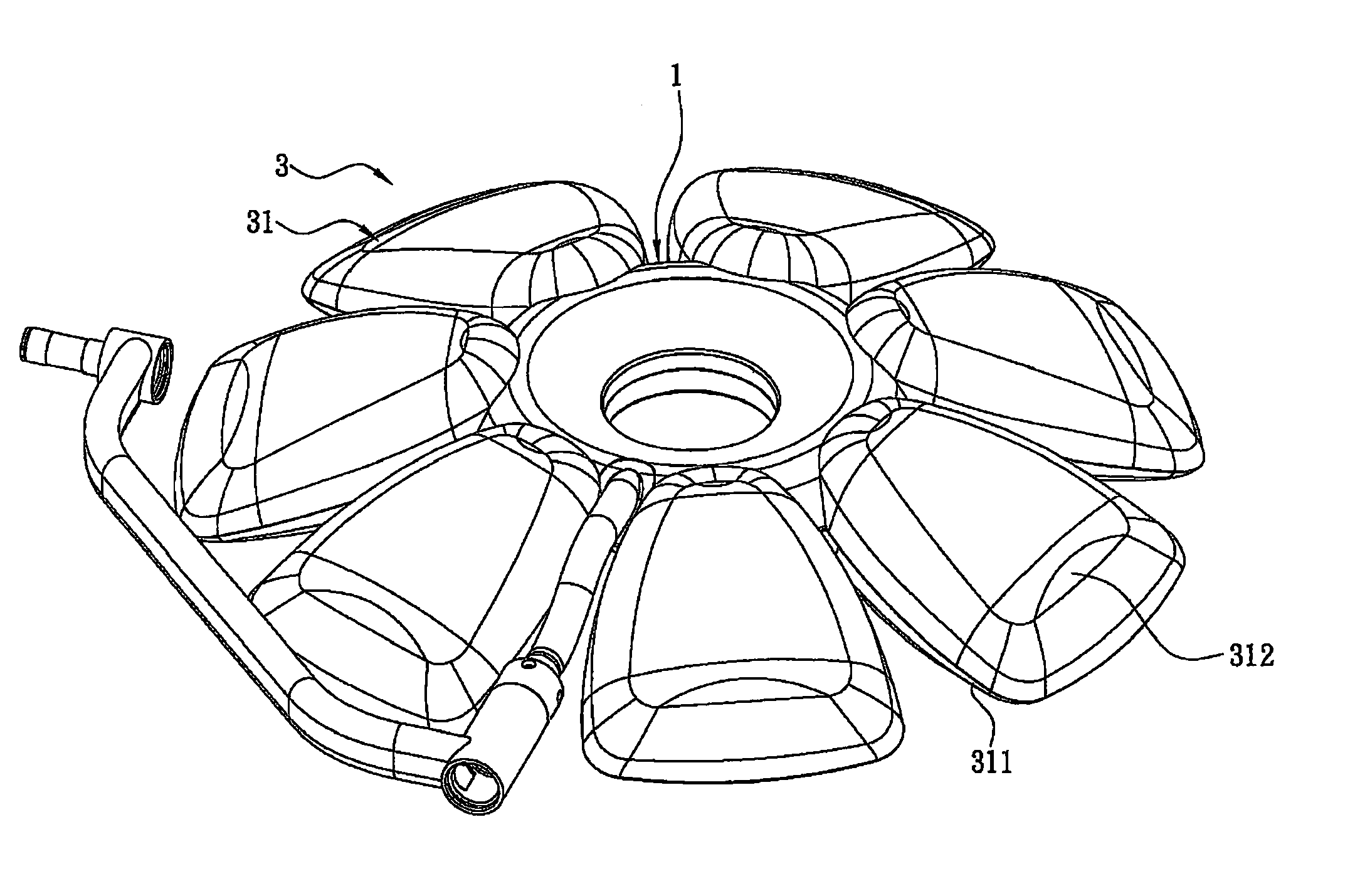
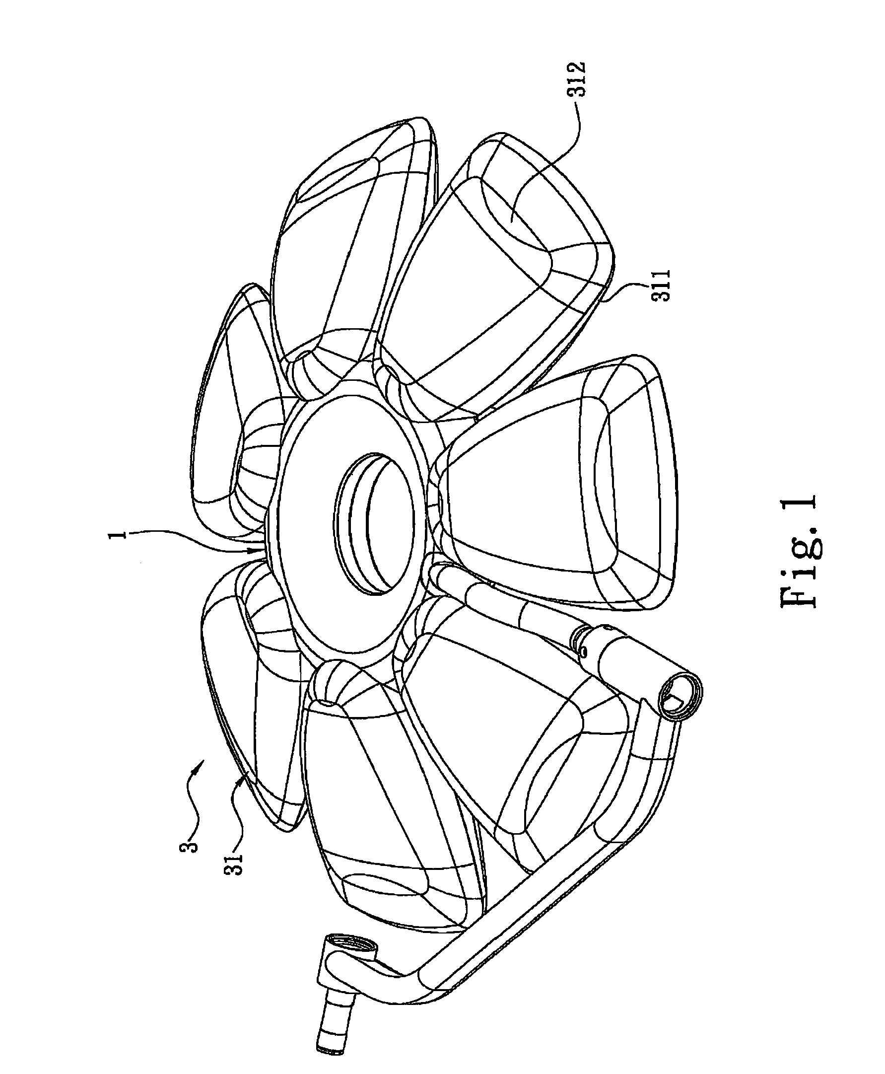
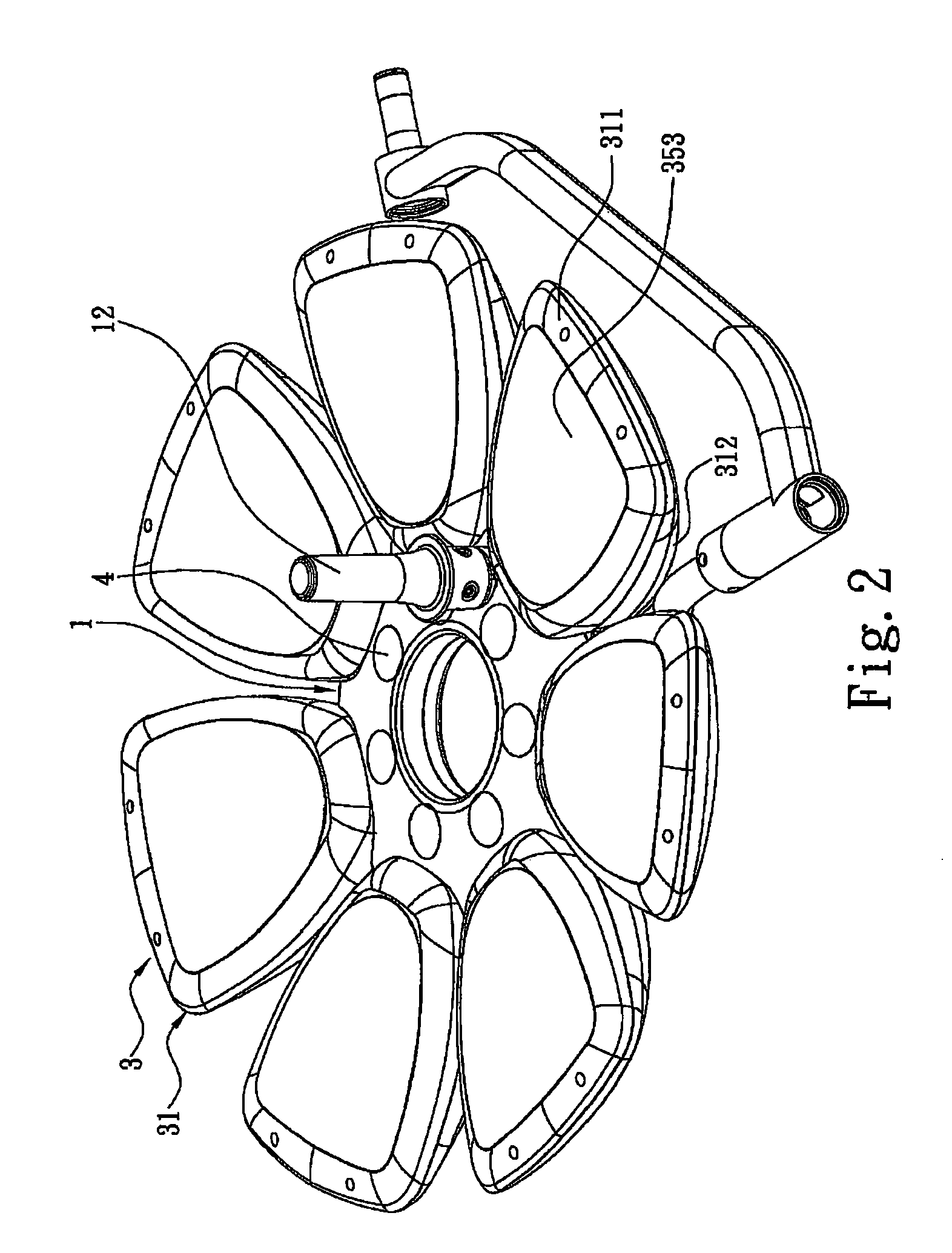
[0023]Referring to FIGS. 1 through 4, a multi-source shadowless operating lamp in accordance with the present invention comprise a central base 1, a link element 2, seven spotlights 3 and seven auxiliary light units 4.

[0024]A light field A is defined below the central base 1 and extends perpendicular to the central base 1. The central base 1 has a gear 11, and a manipulation portion 12 for driving the gear 11 to rotate.

[0025]The link element 2 is received in the central base 1, and has a support rack 21 mounted on the central base 1. A gear rod 22 is connected to the support rack 21 for meshing with the gear 11 of the central base 1. Seven connecting levers 23 extend from the support rack 21 and are spaced a distance apart from each other. Each connecting lever 23 includes a first rotating bar 231 and a second rotating bar 232. An omni-directional joint 233 is mounted on an end of the first rotating bar 231 for connecting with the support rack 21, and a second omni-directional joint...


PUM


Abstract

A multi-source shadowless operating lamp is disclosed, which includes a central base, a link element received in the central base, and a plurality of spotlights mounted on a peripheral of the central base and spaced a distance apart from each other. A light field is defined below the central base and extends perpendicular to the central base. Each spotlight defines a light focus spot through the light field. The focus spots exactly pass the same height in the light field. Each spotlight includes a lamp shell connecting with the central base, a dissipation substrate accommodated in the lamp shell, and a plurality of LED sets. The LED sets at different positions respectively cast light to the focus spot of the spotlight. An angle between the dissipation substrate and the light shell is adjustable to change position of the focus spot of the spotlight relative to the light field.

Description

BACKGROUND OF THE INVENTION[0001](a) Field of the Invention[0002]The present invention relates to a multi-source shadowless operating lamp, and particularly to a multi-source shadowless operating lamp which has dissipation substrates, a plurality of LED (Light Emitting Diode) sets being mounted on the dissipation substrates and having different angles for respectively corresponding to a fixed light field, and a link element automatically adjusting the angles for varying height of light, thereby overlapping a light field and preventing against dust.[0003](b) Description of the Prior Art[0004]Optical light apparatus applied on medical operation is generally shadowless and is distinguished from ordinary illuminative devices. A conventional shadowless operating lamp has a central base on a center thereof, and forms a fixed light field below the central base. A plurality of illumination bodies are symmetrically around the central base. The illumination bodies are pivoted to the central b...

Claims


Application Information

Patent Timeline
Patent Type & Authority Patents(United States)
IPC IPC(8): F21S8/00
CPCF21V14/02F21W2131/205F21Y2101/02Y10S362/804F21Y2115/10
Inventor CHIANG, CHUN-SHEN
Owner MEDILAND ENTERPISE
Learn More