
Printing program that adjusts annotation location and size

a printing program and annotation technology, applied in the field of printing programs, can solve the problems of loss ineffective suppression of commentary string information, and achieve the effect of suppressing the loss of text information and commentary string information without reducing the print size of tex

Inactive Publication Date: 2011-07-05
KYOCERA DOCUMENT SOLUTIONS INC
View PDF6 Cites 2 Cited by
  • Summary
  • Abstract
  • Description
  • Claims
  • Application Information

AI Technical Summary

Benefits of technology

The invention provides a printing program that allows for the attachment of commentary string data to print data without reducing the print size of the text. The program calculates the rendering area of the print data and commentary string data, and checks if the two areas overlap. If there is no overlap, the program changes the commentary string data to edit it in a way that does not overlap with the print data. This prevents loss of text information and commentary string information without reducing the print size of the text. The program also displays a print preview screen to check if the transmission of the print data is acceptable to the user. This prevents the generation of an unwanted print result and ensures that the user is aware of any changes made to the commentary string data.

Problems solved by technology

As a result, the commentary string information may be lost.
Further, the above approach is not effective in suppressing loss of commentary string information because the entirety or a part of the commentary string may be deviated from the effective printing area.

Method used


Image

  • Printing program that adjusts annotation location and size
  • Printing program that adjusts annotation location and size
  • Printing program that adjusts annotation location and size

Examples


first embodiment

[0040]FIG. 9 is a block diagram schematically showing a hardware configuration of an image forming system in accordance with the first embodiment of the invention.

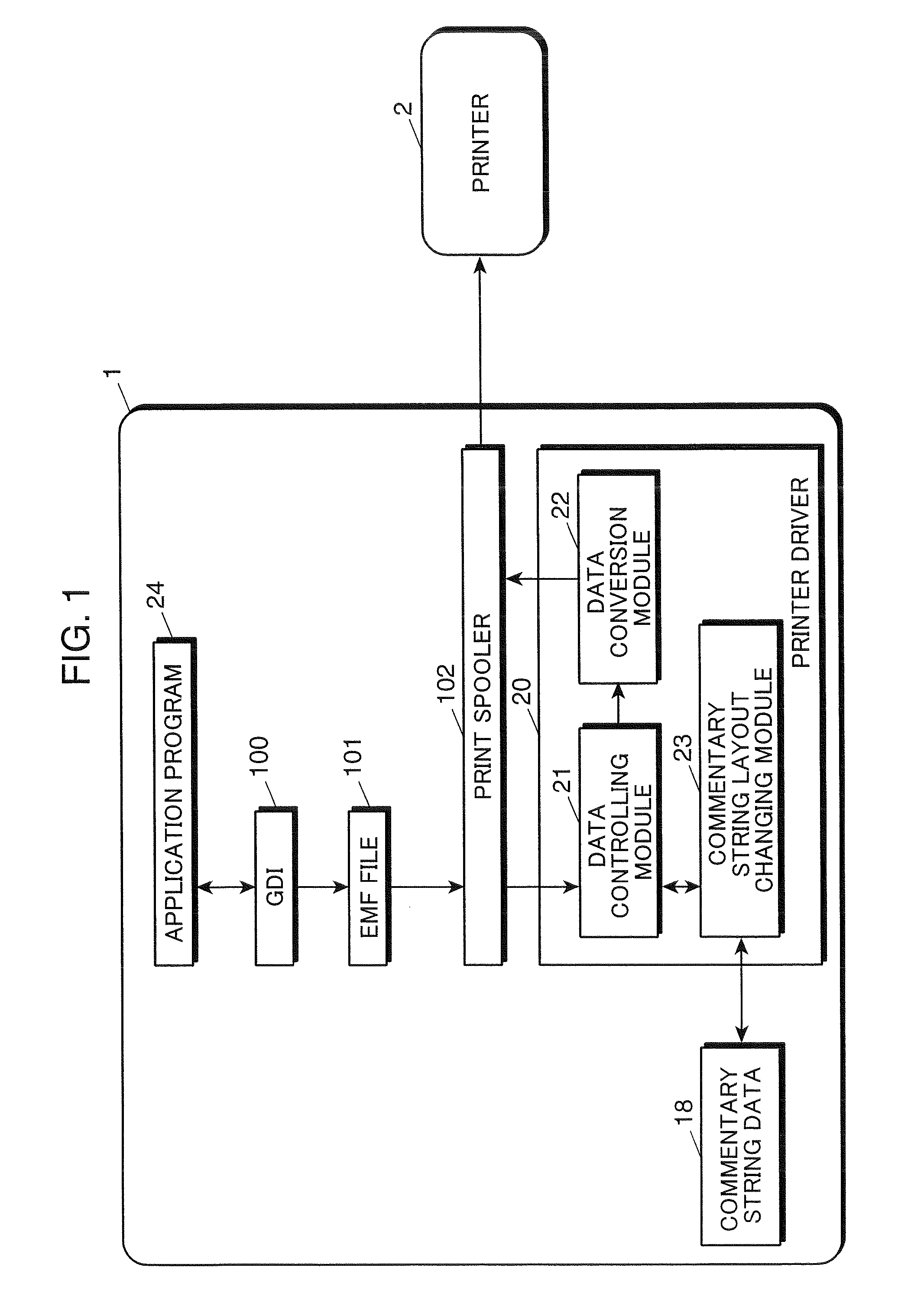
[0041]The image forming system includes a computer 1 such as a personal computer, and a printer 2. The printer 2 is a PDL (page description language) compatible printer. The printer 2 adopts a method of developing print data i.e. PDL data converted by a printer driver 20 into bitmap data by the printer 2 for printing.

[0042]The computer 1 has a CPU (central processing unit) 10 as a processor. An RAM (random access memory) 12 as a storing section or a temporary storage, an ROM 13 as a storing section, an HDD 14 as a storing section, an interactive input device 15 as an input section such as a keyboard or a pointing device, a display device 16, and a communication port 17 such as a USB port or a parallel port are communicatively connected to the CPU 10 via an interface (I / F) section 11. In FIG. 9, plural interfaces are indica...

second embodiment

[0090]In this section, a functional arrangement of an image forming system in accordance with the second embodiment is described. The image forming system is configured in such a manner that print data is spooled in an RAW format, in place of an EMF format.

[0091]FIG. 10 is a functional block diagram schematically showing the image forming system in accordance with the second embodiment.

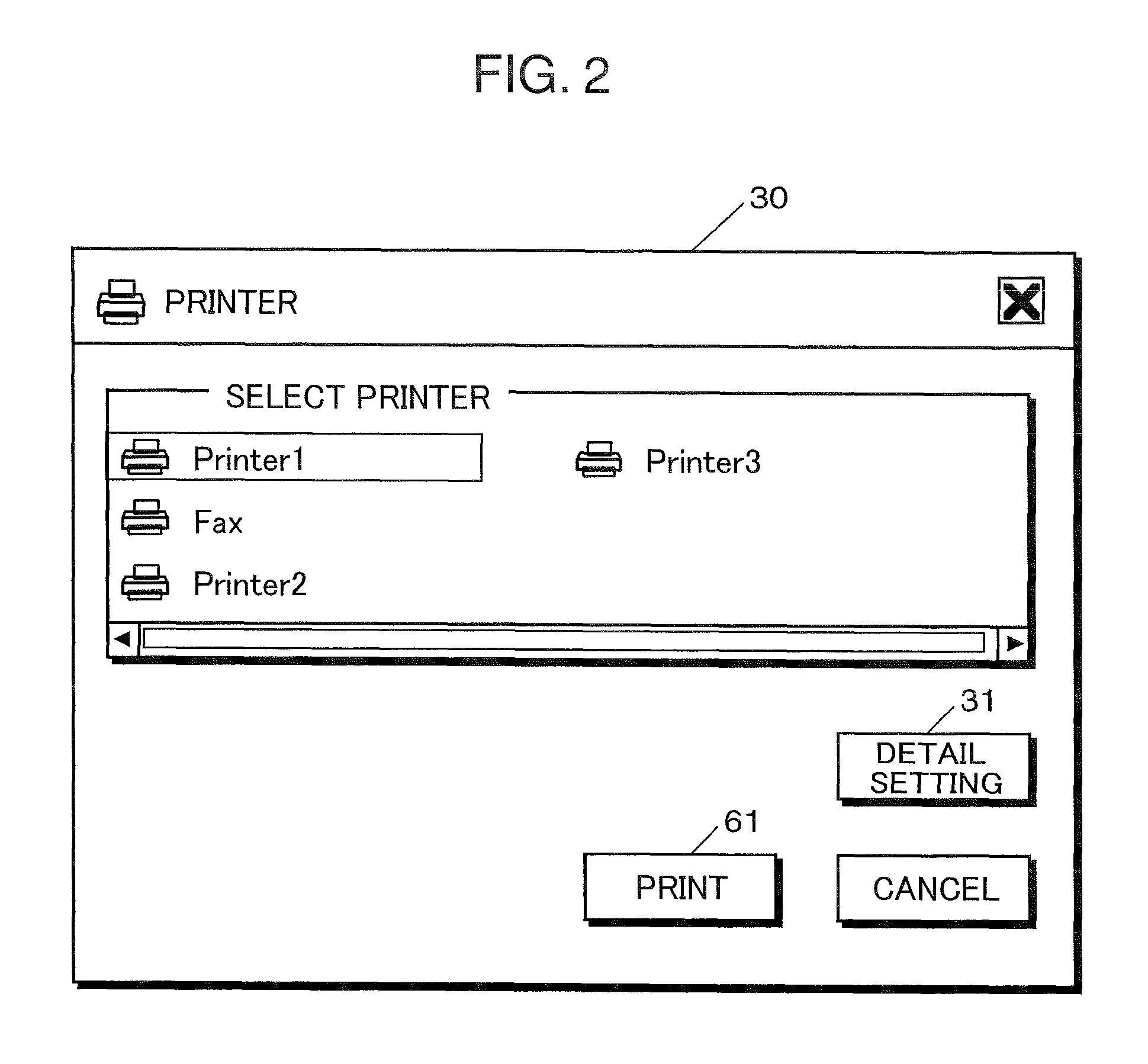
[0092]Similarly to the first embodiment, after a print setting is designated on a print dialog box 30, a print setting dialog box 32, and a header / footer print dialog box 40, the user is allowed to depress the print button 61 shown in FIG. 2. An operation to be executed by the image forming system until the contents of print data is formed on a recording sheet in response to user's depressing the print button 61 is described referring to the functional block diagram shown in FIG. 10.

[0093]In response to user's depressing the print button 61, an application program 24 calls a function of a GDI 100 in c...

third embodiment

[0113]The first and the second embodiments are so configured as to suppress loss of text information and commentary string information without reducing the print size of the text by shifting the commentary string or reducing the size of the commentary string. The arrangements of the first and the second embodiments, however, may have a drawback that an unduly large shifting or an unduly large size reduction of an exceedingly long commentary string makes it difficult to recognize the commentary string.

[0114]In view of the above, in the third embodiment, a commentary string layout changing module 23 is operative to divide a commentary string to be printed into two rows to secure visual recognition.

[0115]In the following, there is described an approach of dividing a commentary string into two rows by the commentary string layout changing module 23.

[0116]The hardware configuration and the system configuration of an image forming system in accordance with the third embodiment are identic...


PUM


Abstract

A computer-readable recording medium recorded with a printing program causes a processor of a computer to calculate a rendering area of print data stored in a storing section of the computer as a primary area based on the print data, and to calculate a rendering area of commentary string data to be attached to the print data as a sub-area. The program then judges whether the primary area and the sub-area overlap, and whether the sub-area deviates from an effective printing area. The commentary string data can be changed so that the primary area and the sub-area do not overlap, and so that the entire sub-area is within the effective printing area, if at least one of the judgment results in the judging step is affirmative. The changed commentary string data then is attached to the print data.

Description

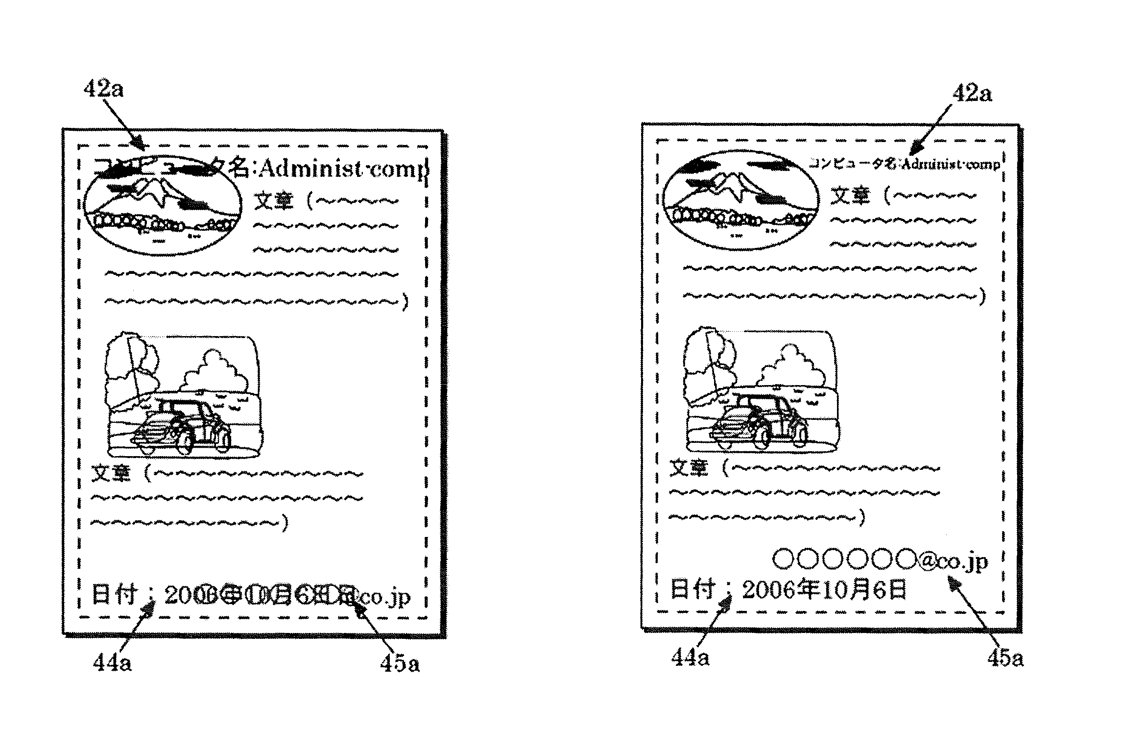
BACKGROUND OF THE INVENTION[0001]1. Field of the Invention[0002]The present invention relates to a printing program having a function of attaching commentary string data relating to a commentary such as a header note or a footer note to print data.[0003]2. Description of the Related Art[0004]Heretofore, there has been known a printer driver with a function of attaching commentary string data relating to a commentary such as a header note or a footer note to print data, in response to accepting print designation by a user on an application software such as a wordprocessor software.[0005]In printing data by utilizing the above function, text information or commentary string information may be lost, if, for instance, as shown in FIG. 7B, a text including an image or the like, and a commentary string overlap each other (see the portion indicated by the reference numeral 42a), or commentary strings overlap each other (see the portions indicated by the reference numerals 44a and 45a).[000...

Claims


Application Information

Patent Timeline
Patent Type & Authority Patents(United States)
IPC IPC(8): G06K15/00G06K9/34H04N1/46
CPCH04N1/00238H04N1/32133H04N2201/0082H04N2201/3225H04N2201/3245H04N2201/3266H04N2201/3271H04N2201/328
Inventor NINO, KENJI
Owner KYOCERA DOCUMENT SOLUTIONS INC
Learn More