Spread spectrum clock interoperability control and inspection circuit
a technology of interoperability control and inspection circuit, which is applied in the direction of generating/distributing signals, pulse techniques, instruments, etc., can solve problems such as the failure of products to meet the limit of radiated emission
- Summary
- Abstract
- Description
- Claims
- Application Information
AI Technical Summary
Benefits of technology
Problems solved by technology
Method used
Image
Examples
second embodiment
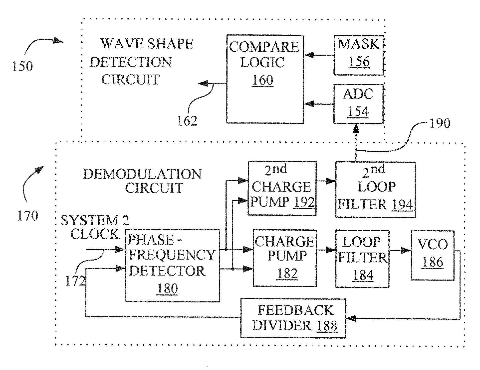
[0049]The second charge pump 192 has its output directed to a second loop filter 194, and its output signal at 190 is the variable voltage that is directed to the analog-to-digital converter 154 in the wave shape detection circuit 150. The mask 156 is essentially equivalent to the mask 106 of FIG. 3, and the compare logic 160 is essentially equivalent to the compare logic 110 of FIG. 3. The output signal from the compare logic in FIG. 4A is at 162. Similar decisions are made by the comparison logic 160, based on the attributes of the mask 156.
third embodiment
[0050]A third embodiment is presented by using a wave shape detection circuit, generally designated by the reference numeral 155 on FIG. 4B, that replaces the ADC with a circuit that compares the wave shape at a number of predetermined profile locations or times. This comparison would be used to determine if the SSCG profile is correct for the optimum shape.
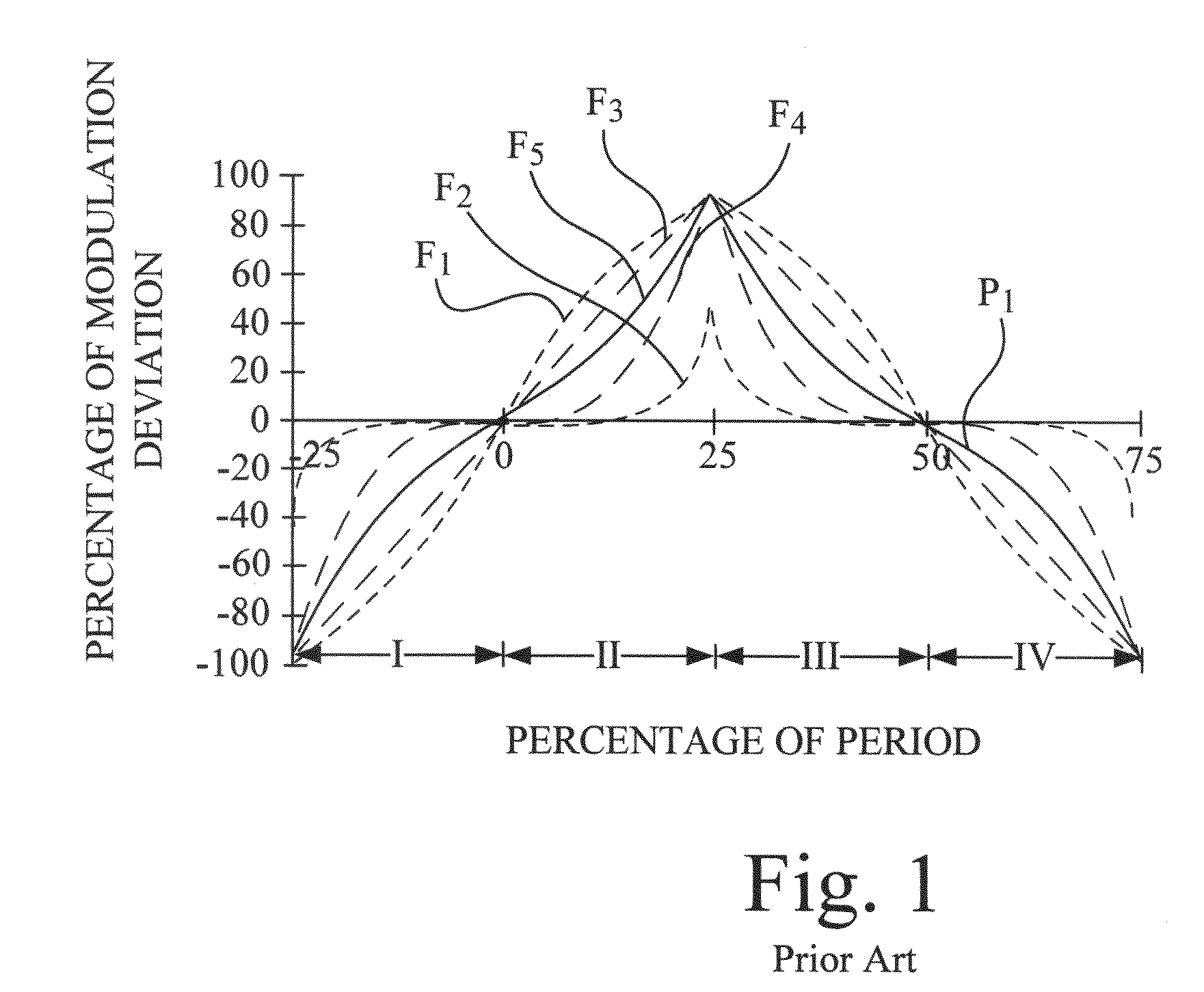
[0051]The first step is to create an analog profile to match one of the shapes found in FIG. 1 (see U.S. Pat. No. 5,488,627 column 9, line 23). The preferred shape is the F5 profile. This can be done by first creating a voltage or current triangular wave. This can be simply done by applying a constant current into a capacitor that starts at the profile average value which creates a positive ramp and continues until the positive peak. At the peak time, the sign of the current source is made negative to cause a negative ramp from that peak. This creates a triangular wave from the zero (0) deviation through the peak and back to the ...
fourth embodiment
[0056]A fourth embodiment is presented by using analog and digital circuitry to be the wave shape detection circuit to measure key aspects of the profile. The key aspects are the period, symmetry, amplitude and inflections of the profile. Referring back to FIG. 1, the period can be determined by finding the time between the zero (0) deviation crossings and adding the positive deviation half period to the negative deviation half period.
[0057]The fourth embodiment is depicted in FIG. 5, which shows a circuit 200 that can be used to determine the positive and negative ½ periods of the modulation waveform; these added together result in the modulation period. Symmetry can be checked by comparing the one-half period values that should be close to the same value if the area above and below the average are the same.
[0058]In the circuit 200, a demodulation circuit 210 sends a signal to a low pass filter 212 and also to a pair of comparators 220 and 224. The low pass filter 212 also outputs ...
PUM
 Abstract
Description
Claims
Application Information
 - R&D
- Intellectual Property
- Life Sciences
- Materials
- Tech Scout
- Unparalleled Data Quality
- Higher Quality Content
- 60% Fewer Hallucinations
Browse by: Latest US Patents, China's latest patents, Technical Efficacy Thesaurus, Application Domain, Technology Topic, Popular Technical Reports.
© 2025 PatSnap. All rights reserved.Legal|Privacy policy|Modern Slavery Act Transparency Statement|Sitemap|About US| Contact US: help@patsnap.com


