
Capacitive electromagnetic flowmeter

a flowmeter and capacitive technology, applied in the direction of liquid/fluent solid measurement, resistance/reactance/impedence, instruments, etc., can solve the problem of electric circuit taking too much space, and achieve the effect of eliminating the need for containmen

Inactive Publication Date: 2011-05-31
YAMATAKE HONEYWELL CO LTD
View PDF6 Cites 8 Cited by
  • Summary
  • Abstract
  • Description
  • Claims
  • Application Information

AI Technical Summary

Benefits of technology

The present invention relates to a capacitive electromagnetic flowmeter that includes an excitation coil, a signal electrode, a field effect transistor, an operational amplifier, a feedback path, a voltage maintaining circuit, a series connection circuit, and a capacitor. The technical effect of this invention is that it eliminates the need for an explosion-proof container and increases the input impedance of the signal pickup circuit, while maintaining the voltages of the field effect transistor at the same level, in terms of alternating current, by using a predetermined constant voltage generated by the flow of an electric current.

Problems solved by technology

Because of this, it is necessary to use a large capacitance capacitor, which is physically large, as the feedback capacitor C2, with not only a problem that the electric circuit will take too much space, but also that it is necessary to house the circuit in a strictly explosion-proof container.

Method used


Image

  • Capacitive electromagnetic flowmeter
  • Capacitive electromagnetic flowmeter
  • Capacitive electromagnetic flowmeter

Examples


Embodiment Construction

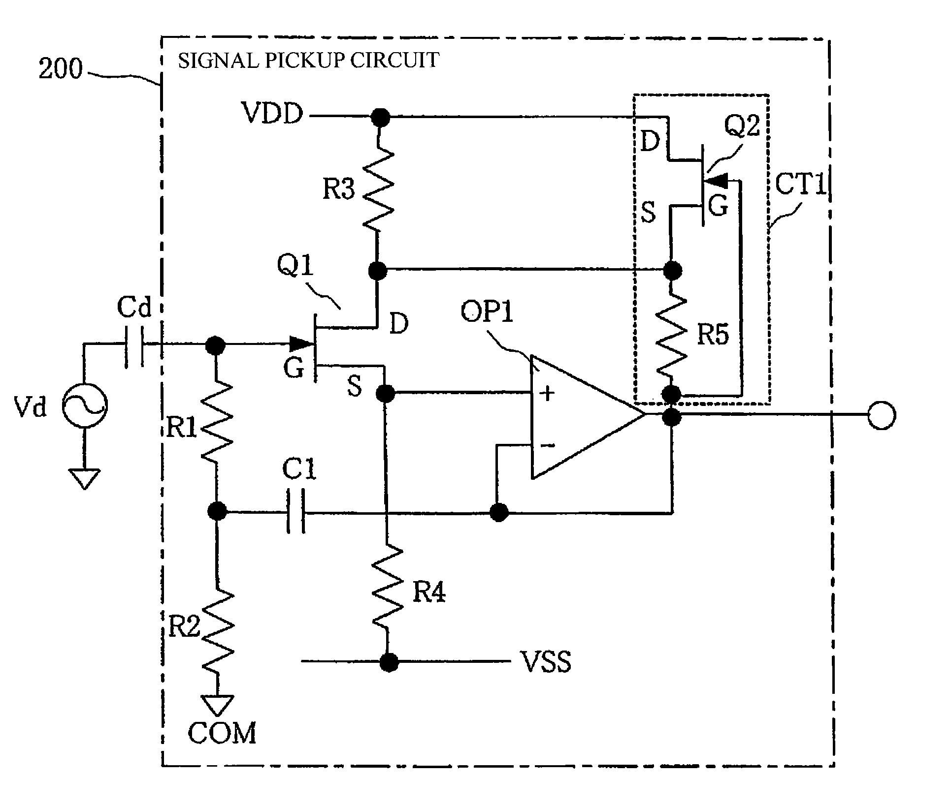
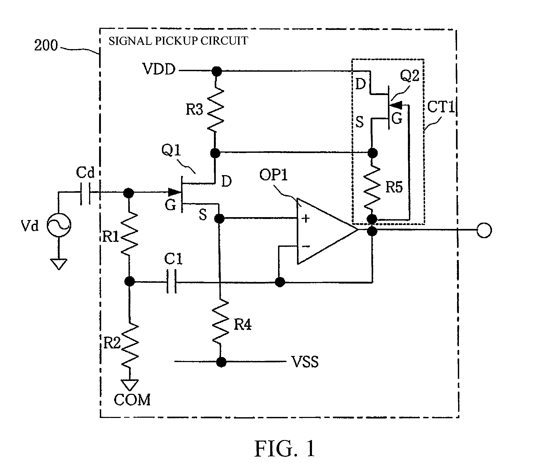
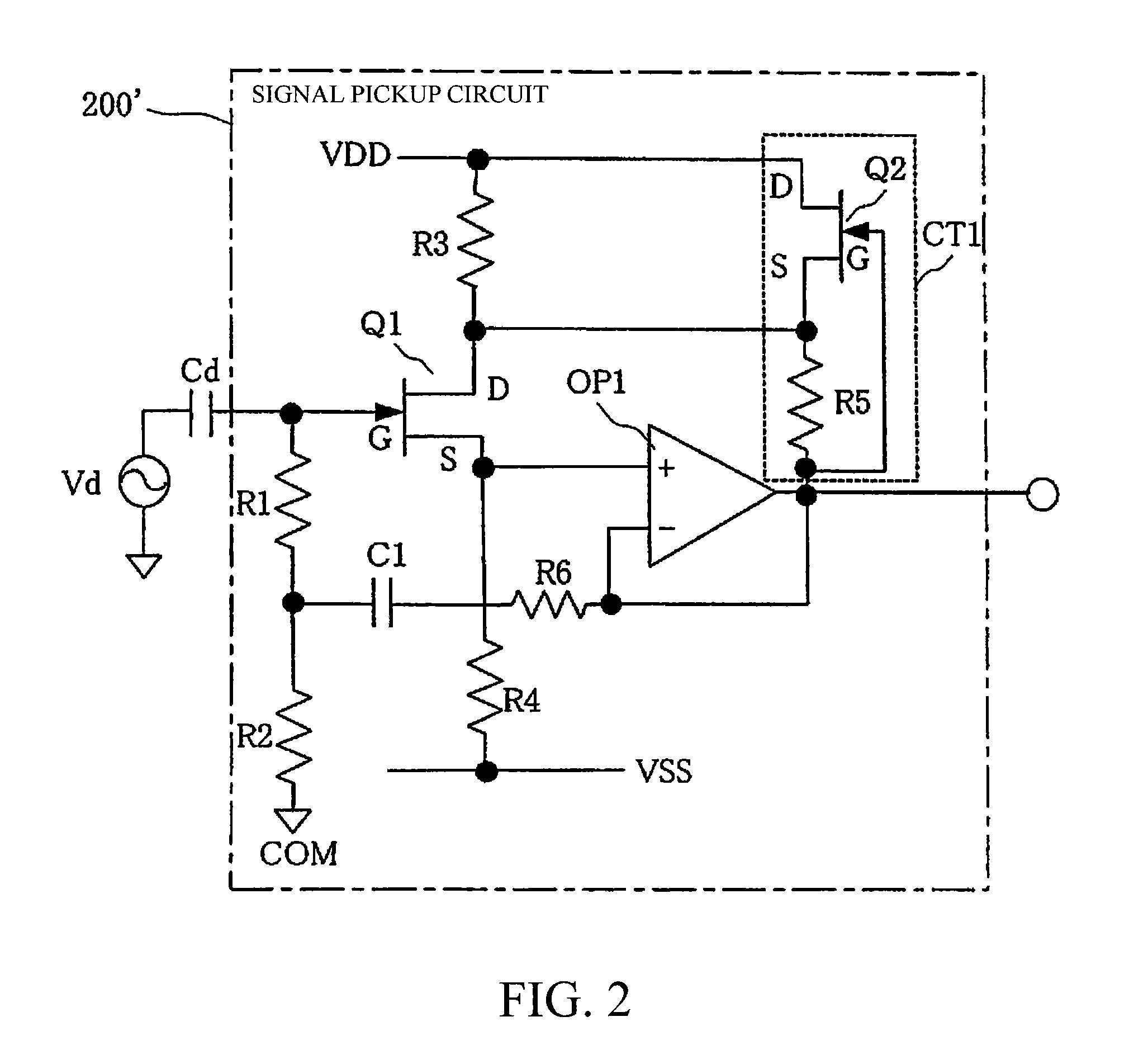
[0027]The present invention will be described in detail below based on the drawings. A capacitive electromagnetic flowmeter according to an embodiment according to the present invention will be described using FIG. 1, FIG. 8A, and FIG. 8B.

[0028]In FIGS. 8A and 8B, 1 illustrate a measuring tube, a non-magnetic pipe 2 (such as, for example, a pipe made out of stainless steel with an insulating resin lining 3 on the inside thereof), 4 is a signal electrode, and 5 is a guard electrode for shielding the signal electrode 4. Two sets of signal electrodes 4 and guard electrodes 5 are provided facing each other in the resin lining 3.

[0029]An excitation coil 6 for producing a magnetic field in a direction that is perpendicular to the direction of flow of the fluid that is flowing within the measuring tube 1 is provided coiled around a core 7. The signal electrodes 4 and the guard electrodes 5 are provided in a direction that is perpendicular to the magnetic field that is produced by the excit...


PUM


Abstract

In a constant current circuit, a constant current is caused to flow through a resistor, thereby causing a constant voltage to occur across the resistor. This constant voltage is then superimposed on an output signal of an operational amplifier that is to be fed back to the drain of a field effect transistor, thereby maintaining the same potential in an AC manner between the output terminal of the operational amplifier and the drain of the field effect transistor. In this way, the gate and drain of the field effect transistor is caused to exhibit the same potential in an AC manner, so that no current will occur through the stray capacitance between the gate and drain of the field effect transistor. As a result, similarly to a case of using a feedback capacitor, the input impedance of the field effect transistor can be raised.

Description

CROSS REFERENCE TO RELATED APPLICATION[0001]This is a U.S. national phase application under U.S.C. §371 of International Patent Application No. PCT / 2007 / 065262, filed Aug. 3, 2007 and claims the benefit of Japanese Patent Application No. 2006-295744, filed Oct. 31, 2006. The International Application was published in Japanese on May 8, 2008 as International Publication No. WO / 2008 / 053624 under PCT Article 21(2) the contents of which are incorporated herein in their entirety.FIELD OF TECHNOLOGY[0002]The present invention relates to a capacitive electromagnetic flowmeter provided with a signal electrode for electrostatic capacitive coupling with a fluid that flows within a measuring tube.BACKGROUND OF THE INVENTION[0003]Conventionally, this type of capacitive electromagnetic flowmeter has an excitation coil for producing a magnetic field in a direction that is perpendicular to the direction of flow of the fluid that flows within the measuring tube, and a signal electrode for electrost...

Claims


Application Information

Patent Timeline
Patent Type & Authority Patents(United States)
IPC IPC(8): G01F1/58G01R27/26
CPCG01F1/60G01F1/588
Inventor HARADA, YUTAKAMITSUTAKE, ICHIROOKUDA, KOUJIINOUE, TAKAKAJITA, TETSUYA
Owner YAMATAKE HONEYWELL CO LTD
Learn More