
Power LED channel letter lighting module

a technology of led channel letter and led light source, which is applied in the field of electronic lighting systems, can solve the problems of relatively short operating life of neon and fluorescent light sources and high operating cost, and achieve the effect of reducing electrolysis and/or interconnection corrosion

Inactive Publication Date: 2011-05-24
J & J ELECTRONICS LLC
View PDF7 Cites 8 Cited by
  • Summary
  • Abstract
  • Description
  • Claims
  • Application Information

AI Technical Summary

Benefits of technology

[0015]In some embodiments of the LED module which incorporate the power regulator, such power regulator may comprise a zener clamped base drive voltage in a full wave rectified voltage applied to the LED(s) to control power dissipation over load and line variations. In other embodiments, the power regulator may comprise a voltage reference and a transistor which operate on full waive rectified alternating current (AC). The inclusion of such power regulator provides better control of current to the LED(s) enables the use of AC voltage between LED serially connected LED modules thereby reducing the potential for electrolysis and / or interconnect corrosion.
[0017]Still further in accordance with the present invention, there are provided methods for operating a series of LED modules, such methods comprising the use of AC voltage between the modules so as to reduce electrolysis and / or interconnect corrosion.

Problems solved by technology

However, such neon and fluorescent light sources have a relatively short operating lives, are fragile, require high voltage (e.g., 7,000 to 15,000 volts for neon) and can be expensive to operate because they consume substantial amounts of power.

Method used


Image

  • Power LED channel letter lighting module
  • Power LED channel letter lighting module
  • Power LED channel letter lighting module

Examples

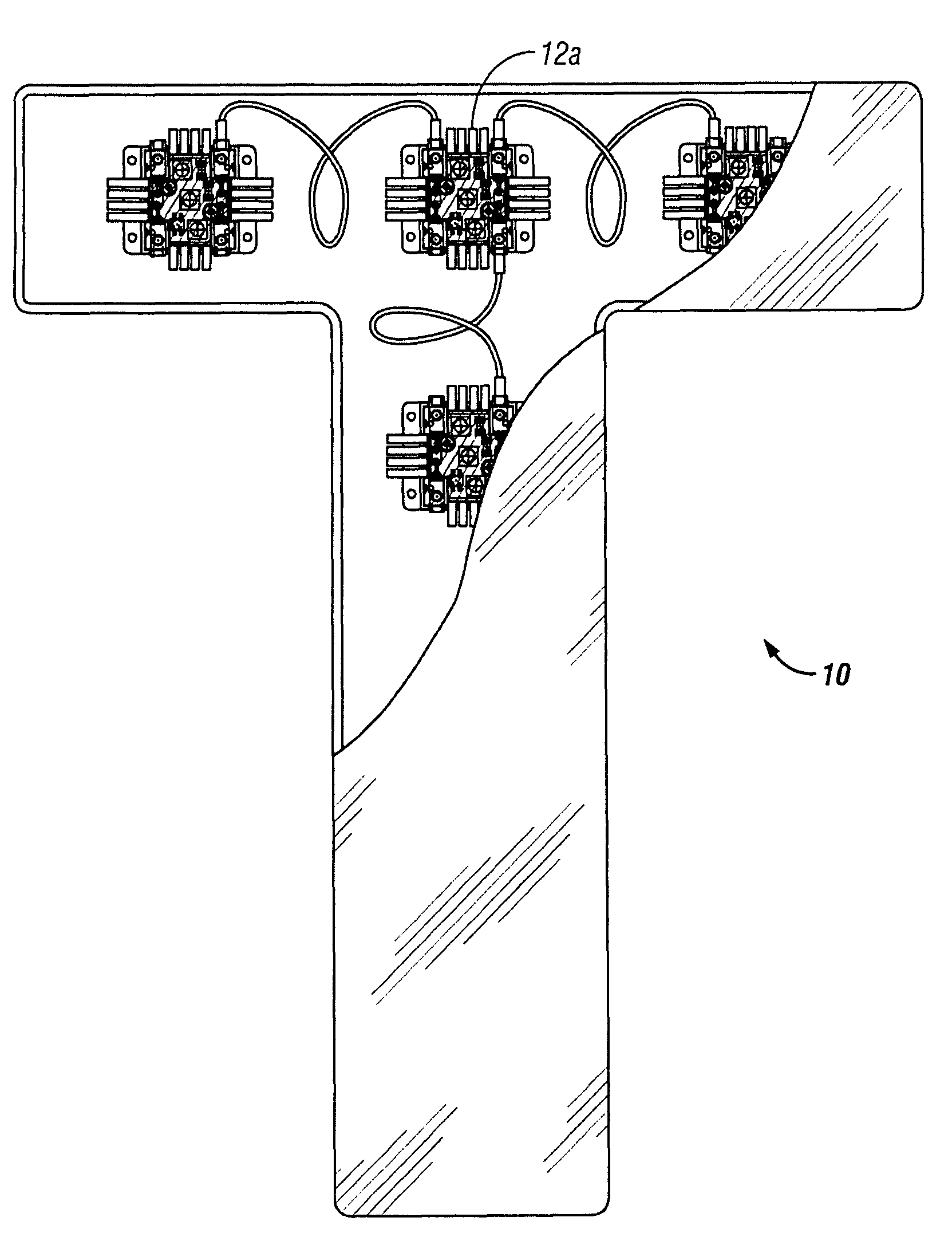
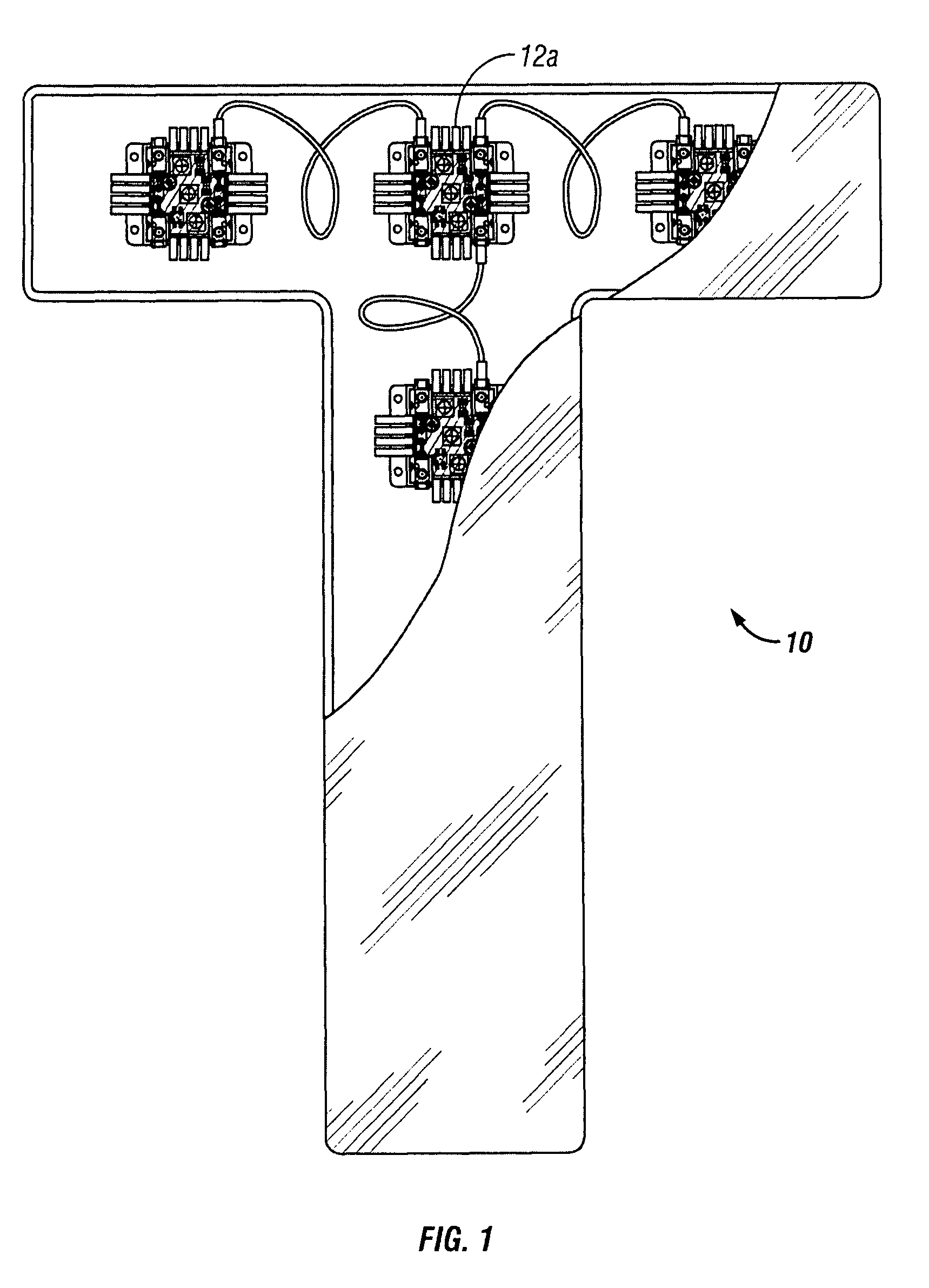

Embodiment Construction

[0027]The following detailed description and examples, as well as the accompanying drawings, are illustrative in nature. They are provided for the purpose of describing some, but not all, possible embodiments or examples of the invention and shall not be construed as limiting the scope of the invention in any way.

[0028]LED lighting for use in channel letters is currently available. Such channel letter LED lighting typically consists of a series of modules, each module consisting of a circuit board with a group of LEDs mounted thereon. These LED modules are wired in series and mounted within the channel letters such that the LEDs provide uniform light which is cast through a translucent panel on the face of each letter.

[0029]The present invention provides high power LED devices and systems useable for lighting relatively large channel letters and for other lighting applications such as light box illumination, back lighting, cove lighting, signage lighting, integration into luminaries...


PUM


Abstract

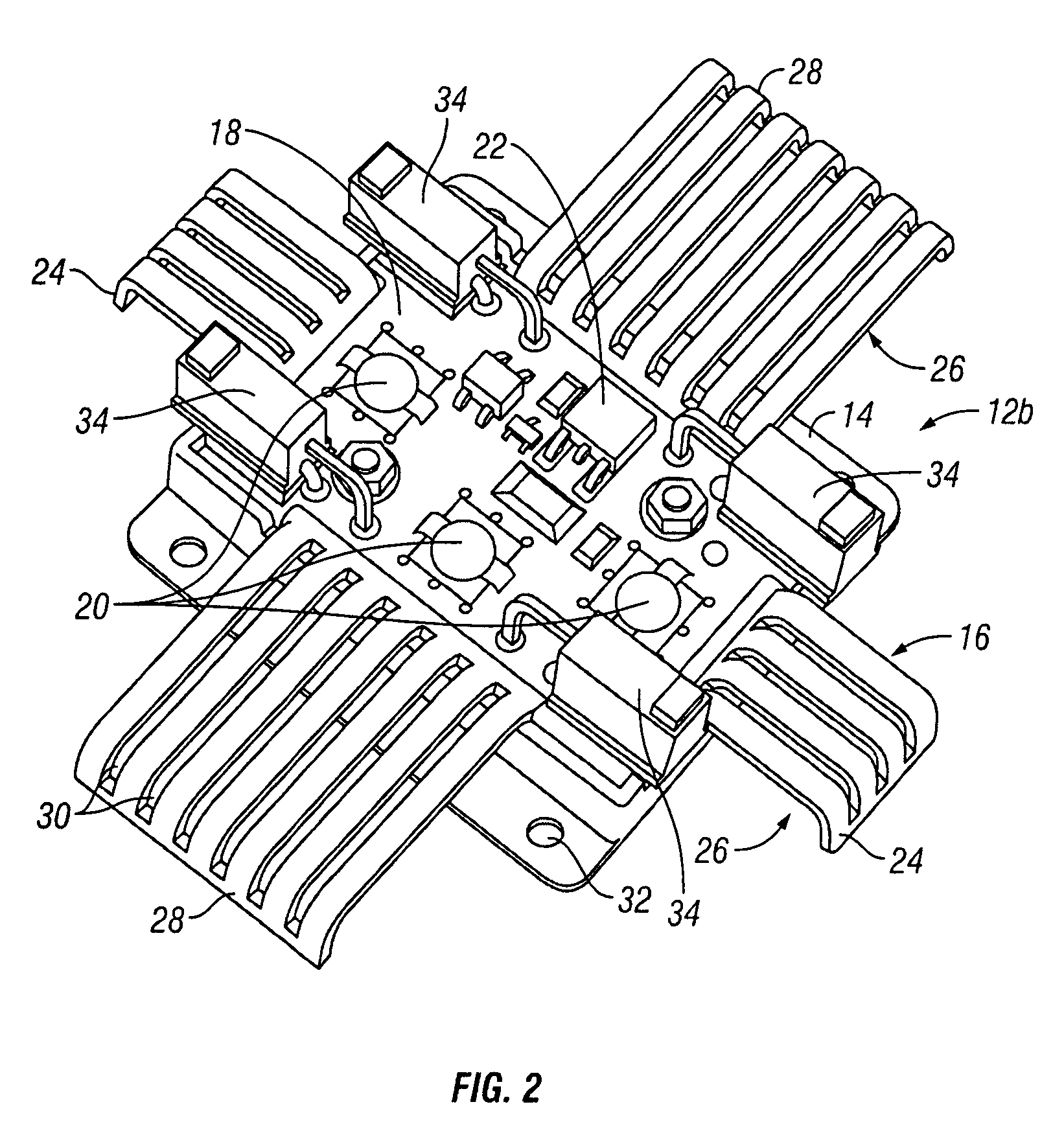
Light Emitting Diode (LED) modules that generally comprise a) a frame or housing, b) a circuit board that comprises a solid state circuit and is mounted on the frame or in the housing, c) one or more LEDs connected to the solid state circuit and d) at least one of the following: i) a heat sink that extends outboard (e.g., outside the outer boundaries of) the housing or frame; and / or ii) a power regulator which controls power dissipation over load and line variations and / or a pulse regulation circuit which to regulates current pulses in the LEDs in the unfiltered full wave unregulated 60 cycle Hz alternating current (AC). These LED modules may be connected to one another in series and my operate on AC current. In some embodiments, these LED modules are used for channel letter lighting and other illuminated signage applications.

Description

RELATED APPLICATION[0001]This patent application claims priority to U.S. Provisional Application No. 60 / 773,830 filed Feb. 15, 2006, which is expressly incorporated herein by reference.FIELD OF THE INVENTION[0002]This invention relates generally to electronic lighting systems and more particularly to light emitting diode (LED) systems that are useable for lighting channel letters and for other applications.BACKGROUND OF THE INVENTION[0003]LEDs are a solid state lamps that use semiconductor material instead of a filament or neon gas. When compared to traditional (i.e., fluorescent or incandescent) light bulbs, LEDs offer a number of advantages. For example, because LEDs operate on low voltage and consume less power, they are less expensive to operate and generate significantly less heat than traditional light bulbs. Also, because LEDs are of solid state design, they are more durable and less likely to break than traditional bulbs. Another advantage of LEDs is their long life. Some LE...

Claims


Application Information

Patent Timeline
IPC IPC(8): F21V29/00
CPCG09F13/22G09F9/33
Inventor WRAY, DONALD LEE
Owner J & J ELECTRONICS LLC
Learn More