Coating layer thickness measurement mechanism and coating layer forming apparatus using the same

a coating layer and measurement mechanism technology, applied in the direction of apparatus for force/torque/work measurement, electrical/magnetic thickness measurement, instruments, etc., can solve the problem of difficult rotation of the electrode, the thickness of the coating cannot be changed or occurrence of damage, and the thickness of the coating cannot be free of variation or damage, etc. problem, to achieve the effect of suppressing the variation in the speed of feeding a base material, minimizing the influence of the sway of the measurement surfa

Inactive Publication Date: 2011-05-24
SUMITOMO ELECTRIC IND LTD
View PDF13 Cites 1 Cited by
  • Summary
  • Abstract
  • Description
  • Claims
  • Application Information

AI Technical Summary

Benefits of technology

[0009]In order to suppress such conventional problems as described above, an object of the present invention is to provide a mechanism capable of measuring a thickness of a coating layer with higher accuracy by suppressing variation in a speed of feeding a base material in a treatment portion and minimizing influence of sway of a measurement surface in a direction of thickness at a thickness sensing portion during feeding, as well as a coating layer forming apparatus using the same.
[0013]The measurement mechanism according to the present invention is suitably used in forming the coating layer on the conductive elongate base material in the coating treatment base station while the base material is fed, and by increasing tension only in the vicinity of the sensing portion, influence during sensing, of sway of the measurement surface of the coating layer caused by feeding can be minimized. Therefore, the thickness of the coating layer can be measured with higher accuracy. In addition, as the tension is applied at the sensing portion before and after the base station, the speed of feeding the base material in the base station can more reliably be controlled within the desired range, and chances of damage of the layer due to change in the speed or the like can also be suppressed further, as compared with the conventional example. Thus, as reliability of thickness data obtained in the sensing portion is improved by using the measurement mechanism according to the present invention, not only variation in the speed of forming the coating layer can be suppressed by controlling the feeding speed in the base station as above, but also a coated material smaller in variation in the thickness in a direction of length can be obtained by feedback of the data to a system for controlling a manufacturing parameter for forming the layer, such as a temperature of the base station.

Problems solved by technology

Among others, it is difficult to adjust the balance of feeding tension when a thin layer is to be formed with high dimensional accuracy on the surface of the elongate base material in the form of a tape or fiber.
These means, however, cannot be free from variation in thickness of the layer or occurrence of damage, as the speed of the base material is varied due to change over time in an outer diameter of a feeding portion on the supply side and on the recovery side.
With this means, however, in particular, it is difficult for rotation of the electrode to follow unevenness of the layer surface, and accuracy in measurement is lowered.
With this means, however, particularly if uneven base material surface is moving, the displacement gauge cannot immediately follow the movement.
Accordingly, time lag from sensing of a distance by the sensor is caused, which leads to lower accuracy in measurement.
Therefore, if the base material is out of a limited range of base material conditions, variation in thickness of the layer or occurrence of damage is unavoidable.

Method used


Image

  • Coating layer thickness measurement mechanism and coating layer forming apparatus using the same
  • Coating layer thickness measurement mechanism and coating layer forming apparatus using the same
  • Coating layer thickness measurement mechanism and coating layer forming apparatus using the same

Examples


first example

Formation of Si Vapor-Deposited Layer on Metal Foil Tape

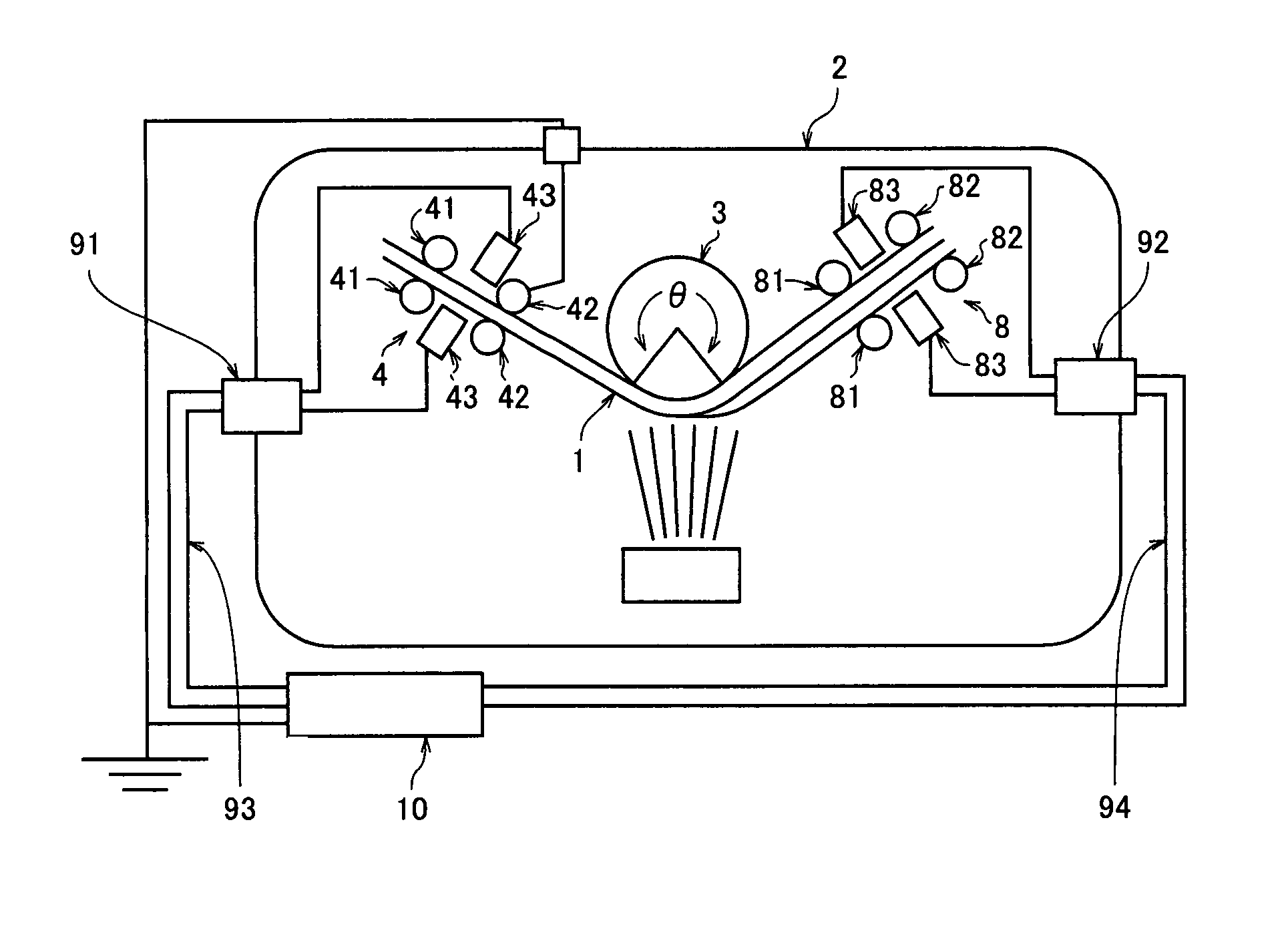
[0027]Referring to FIG. 1, a base material 1 formed as a conductive film is fed from a supply side roller (not shown) placed outside a vacuum chamber 2 on the right in the drawing to a roller 3 in the treatment base station placed inside the vacuum chamber, and an Si vapor-deposited layer or the like is formed on the surface thereof. Thereafter, base material 1 is wound and recovered by a recovery side roller (not shown) placed outside the vacuum chamber on the left in the drawing. The supply side roller is driven, for example, by a motor through an electromagnetic torque control mechanism, and set to transmit tension T1 of force in the direction opposite to the feeding direction to base material 1. On the other hand, the recovery side roller is driven by a motor through an electromagnetic torque control mechanism, and set to transmit tension T2 of force in the feeding direction to base material 1. Roller 3 at the treatment bas...

second example

Formation of Various Vapor-Deposited Layers on Metal Foil Tape and Feedback of Measurement Value to Manufacturing System

[0036]Base Material 1, that is Formed as Pure Copper Foil, has a Width of 130 mm, a thickness of 10 μm, a length of 500 m, and surface roughness Ra of 2 μm, and was used in the first example, was prepared. The conditions substantially the same as in the first example were set, tension T3 to be applied at sensing portion 4, 8 was set to 200 MPa, and layers of various materials shown in the field of material for “coating layer” in Table 2 were vapor-deposited on the base material surface to an average thickness of approximately 5 μm.

[0037]If the specific resistance of the material is greater than a specific resistance of a semiconductor region, change in capacitance ΔC (ΔC / Δp) due to change in specific resistance Δρ becomes smaller, and change in thickness value Δt measured by the capacitance-type sensor also becomes smaller. Therefore, according to the measurement m...


PUM

PropertyMeasurementUnit
Raaaaaaaaaaa
Raaaaaaaaaaa
Raaaaaaaaaaa

Abstract

In a measurement mechanism for continuously measuring a thickness of a coating layer, provided in an apparatus for forming the coating layer on a conductive elongate base material in a coating treatment base station while the base material is fed, a sensing portion for measuring a capacitance value of the coating layer is arranged before and after the base station, and tension applied to the base material at the sensing portion is set to be greater than tension applied to the base material at the base station. Thus, in forming the coating layer on the elongate base material while the base material is continuously fed, variation in a feeding speed is suppressed, influence of sway of a measurement surface in a direction of thickness at the thickness sensing portion during feeding is minimized, and a thickness of the coating layer can be measured with higher accuracy.

Description

BACKGROUND OF THE INVENTION[0001]1. Field of the Invention[0002]The present invention relates to a thickness measurement mechanism and a coating layer forming apparatus using the same, for forming a coating layer in a prescribed thickness range on an elongate base material while it is fed.[0003]2. Description of the Background Art[0004]A feeding mechanism provided with a treatment base station (hereinafter, simply also referred to as a base station) for forming a coating layer on a base material surface continuously at a prescribed speed by using physical or chemical means while conductive elongate base materials of various cross-sectional shapes are fed is used for forming a layer to a thickness in a prescribed range over the entire length of the base materials. Here, examples of the base material include various materials ranging from a soft material such as copper, aluminum, or resin containing metal filler to a hard material such as tungsten or steel. In such a feeding mechanism...

Claims


Application Information

Patent Timeline
Patent Type & Authority Patents(United States)
IPC IPC(8): B05C5/02
CPCC23C14/562C23C14/545G01B7/06G01B21/08
Inventor AWATA, HIDEAKIEMURA, KATSUJIYOSHIDA, KENTARO
Owner SUMITOMO ELECTRIC IND LTD
Why Eureka
Try Eureka