
Mass spectrometer

a mass spectrometer and mass spectrometer technology, applied in the field of mass spectrometers, can solve the problems of reducing the amount of ions to be analysed, affecting the efficiency of ion production, and possible mixing of products with sample molecules, so as to improve the efficiency of producing ions originating from sample molecules concerned, the effect of improving the efficiency of heat decomposition and reducing nois

Active Publication Date: 2011-05-10
SHIMADZU CORP
View PDF8 Cites 6 Cited by
  • Summary
  • Abstract
  • Description
  • Claims
  • Application Information

AI Technical Summary

Benefits of technology

The present invention aims to provide a mass spectrometer that can alleviate the influence of radiation heat from the filament and improve detection sensitivity by efficiently extracting ions produced in the ionization chamber to the outside of the same chamber and using them for mass analysis, while alleviating the influence of the radiation heat.

Problems solved by technology

However, if the a portion of the wall of the ionization chamber is locally heated as explained earlier until its temperature abnormally rises to a specific level, the metallic material constituting the wall of the ionization chamber becomes activated and produces a decomposition product, and this decomposition product may possibly be mixed with the sample molecules and create a noise.
The local heating is also unfavorable that it produces an uneven temperature distribution within the ionization chamber, which deteriorates the ion production efficiency.
The application of this potential to the filament creates an external electric field, which penetrates into the ionization chamber and disturbs the electric field present within the same chamber.
This disturbance of the latter electric field prevents ions produced within the ionization chamber from being extracted to the outside of the ionization chamber in an intended manner, which causes a decrease in the amount of ions to be analyzed and deteriorates the ion detection efficiency.

Method used


Image

  • Mass spectrometer
  • Mass spectrometer
  • Mass spectrometer

Examples


Embodiment Construction

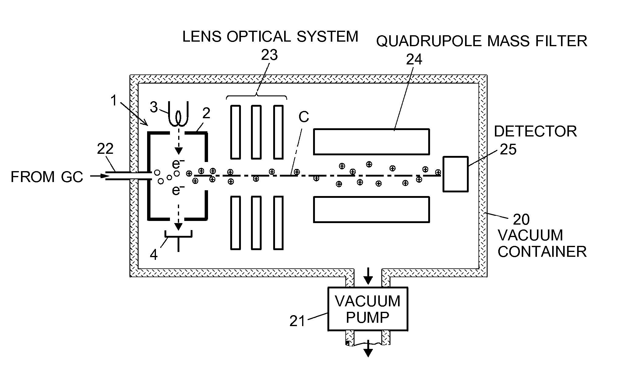
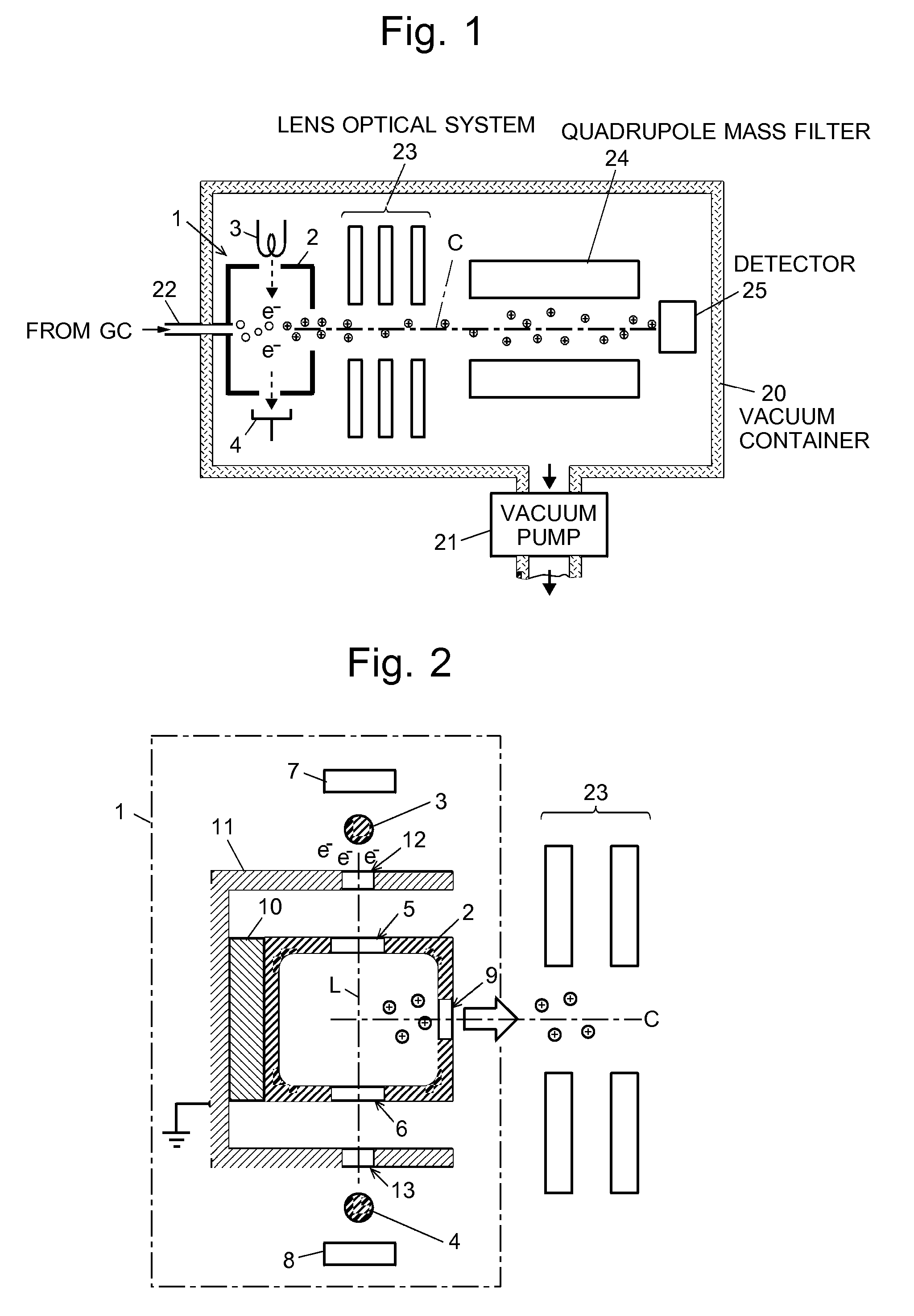
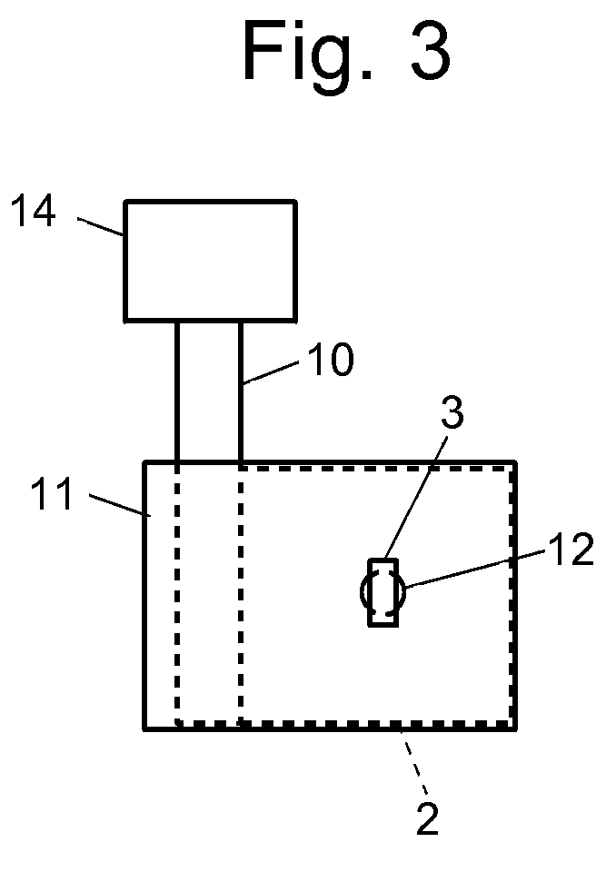
[0022]A mass spectrometer according to an embodiment of the present invention is hereinafter described with reference to the attached drawings. FIG. 1 is an overall configuration diagram of the mass spectrometer of the present embodiment, FIG. 2 is a vertical sectional view showing the detailed structure of an ion source, and FIG. 3 is a top view of the ion source. The ion source in the mass spectrometer of the present embodiment is an ion source that performs electron ionization.

[0023]In FIG. 1, the vacuum container 20 is a substantially hermetically sealed container, which is evacuated by a vacuum pump 21. Contained in this container are an ion source 1, a lens optical system 23, a quadrupole mass filter 24 and an ion detector 25, all being arranged along an ion optical axis C. A sample, such as a sample gas coming from the column of a gas chromatograph (not shown), is supplied through an appropriate interface and the introduction pipe 22 into the ion source 1. The sample molecule...


PUM


Abstract

An electrically conductive heat-blocking plate 11 with an opening 12 for allowing thermions to pass through is provided between a filament 3, whose temperature can be as high as 2000° to 3000° C., and an ionization chamber 2. The heat-blocking plate 11 is thermally connected via an aluminum block 10 to a heater for maintaining the ionization chamber 2 within a range temperature from 200° to 300° C., and also electrically set at a ground potential, which is approximately equal to the potential of the ionization chamber 2. The heat-blocking plate 11 blocks the radiation heat that the filament 3 emits when energized. Thus, the wall of the ionization chamber 2 is prevented from being locally heated to an abnormally high temperature. As a result, the inner space of the ionization chamber 2 is maintained at an approximately uniform temperature, and the noise due to the decomposition of a metallic material by abnormal heating is prevented. The heat-blocking plate 11 also prevents a thermion-accelerating electric field from penetrating through an electron injection port 5 into the ionization chamber 2 and impeding the extraction of ions produced within the ionization chamber 2. Thus, the ion extraction efficiency is also improved.

Description

TECHNICAL FIELD[0001]The present invention relates to a mass spectrometer, and specifically to the structure of an ion source for ionizing sample molecules.BACKGROUND ART[0002]A mass spectrometer is a device that ionizes molecules or atoms of a sample, then separates the resultant ions according to their mass-to-charge ratio and detects these ions. Various methods for ionizing sample molecules have been developed to date, and electron ionization (EI) is one of the most generally used methods. In electron ionization, sample molecules are introduced into an ionization chamber of a comparatively small capacity, which is placed under a vacuum atmosphere. A filament for generating thermions is provided outside this ionization chamber, and thermions thereby generated are accelerated and injected into the ionization chamber. These thermions come in contact with the sample molecules to ionize these molecules within the ionization chamber. The ions thus produced within the ionization chamber...

Claims


Application Information

Patent Timeline
Patent Type & Authority Patents(United States)
IPC IPC(8): B01D59/44H01J49/10H01J7/24H01J49/04
CPCH01J49/0468H01J49/147H01J27/205
Inventor KAWANA, SHUICHISHIMOMURA, MANABU
Owner SHIMADZU CORP
Learn More