
Method for controlling temperature in multiple compartments for refrigerated transport

a refrigeration system and multiple compartment technology, applied in the field of refrigerated transport compartments, can solve the problems of reducing the electrical power consumption of the refrigeration system at startup and/or under high, and reducing the electrical power consumption of the refrigeration system in the second compartmen

Active Publication Date: 2011-05-10
CARRIER CORP
View PDF4 Cites 14 Cited by
  • Summary
  • Abstract
  • Description
  • Claims
  • Application Information

AI Technical Summary

Benefits of technology

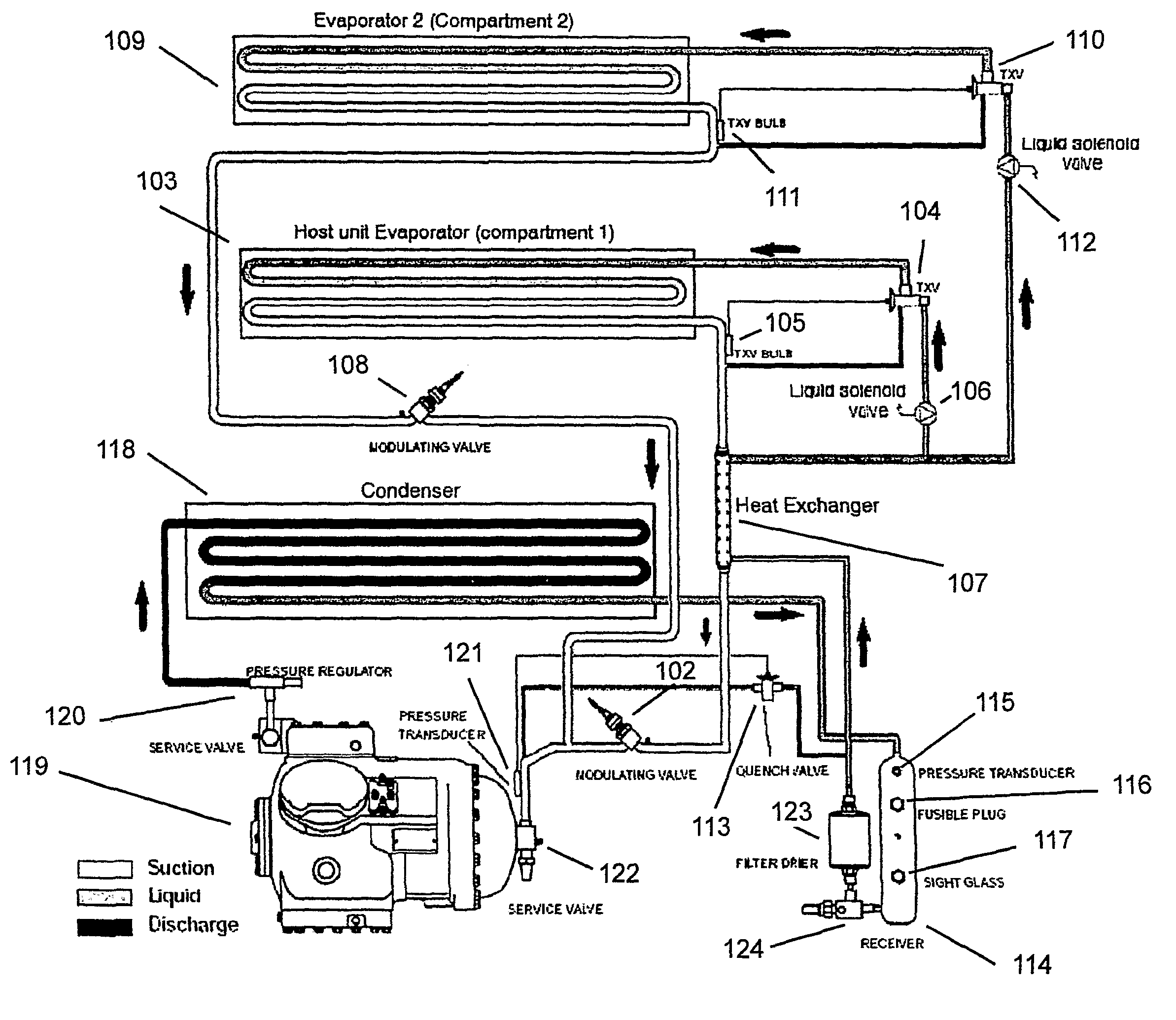
The patent describes a refrigerated transport system that uses a common compressor to cool multiple compartments. The system includes a primary compartment evaporator and a secondary compartment evaporator that work together to control the temperature in each compartment. The system also prioritizes certain compartments and limits the flow of refrigerant to those with the highest priority, ensuring that they are always cooled to the desired temperature. The technical effect of this system is that it allows for precise temperature control in multiple compartments, improving efficiency and ensuring consistent cooling.

Problems solved by technology

This method of cycling the secondary evaporator liquid refrigerant line on and off to control the temperature in the secondary compartment cannot achieve the temperature regulation tolerance that is needed in many applications.
Another problem involving multiple compartment transport refrigeration systems is how to apportion the available cooling capacity at startup and / or under high load conditions, such as when the ambient temperature is very high.
Yet another problem is to limit the electrical power consumption of a multiple compartment transport refrigeration system at startup and / or under high load conditions, such as when the ambient temperature is very high.
For example, ocean going container ships may have power limits and / or circuit breakers that limit the ampacity of the electrical power supply line to each refrigerated transport container.

Method used


Image

  • Method for controlling temperature in multiple compartments for refrigerated transport
  • Method for controlling temperature in multiple compartments for refrigerated transport
  • Method for controlling temperature in multiple compartments for refrigerated transport

Examples


example 1

[0026]The flow chart of FIG. 2A shows an exemplary algorithm to perform the aforementioned prioritization and apportioning of refrigerant during a temporary situation where the transport refrigeration system cooling capacity is insufficient to maintain both compartments at setpoint temperature. Paths of prioritizing actions depend on whether the priority compartment is a freezer compartment or a perishable goods compartment.

[0027]In the case of a freezer compartment, prioritizing actions are only required if the freezing temperature reaches a still frozen safety “ceiling”. As long as the freezing temperature is below the ceiling, there is no significant deterioration of the frozen goods. This path is shown by the “yes” arrow indicating a freezer compartment temperature below the ceiling that results in a still unrestricted flow of refrigerant to a lower priority secondary compartment. Note that even though in this case the secondary compartment has been deemed of lower priority, the...

example 2

[0030]The algorithm illustrated by the flow chart of FIG. 2B shows how according to another embodiment of the invention prioritization can be accomplished where the transport refrigeration system electrical load has reached an electrical current limit. Once an electrical current limit is reached, first the remote compartment refrigerant flow is restricted by holding a pre-defined remote compartment delta T (as can be accomplished by modulating the refrigerant flow with an ESMV). If the limit is no longer exceeded, no further action need be taken. Or, if the limit is still exceeded, the prioritized compartment can also be brought to a pre-determined delta T by also restricting the flow of refrigerant to the priority compartment. If the current limit is still exceeded, in a near worst case situation, refrigerant flow can be restricted to an absolute minimum flow (but, not zero flow) to both compartments.

[0031]Note that in either the case of insufficient cooling or the case of excessiv...

example 3

[0032]A test was conducted to show how modulating the suction pressure from a secondary evaporator compares to prior art technology where secondary compartment temperature control has been achieved by cycling on and off the refrigerant flow to the supply line of the secondary evaporator. FIG. 3 shows data for a test of a two compartment refrigerated transport having a host compartment and a remote compartment. The temperature of the host compartment was set to a setpoint of 1.7° C. and the temperature of the remote compartment was set to a setpoint temperature of 0° C. H-SMV is the modulation position of the host SMV, and R-SMV is modulation position of the remote SMV. SMV position over time is represented on a scale having a fully opened position at the top of the graph and a nearly fully closed position at the bottom of the graph. RTS and STS refer to a return temperature sensor and a supply temperature sensor on the host (H) and the remote (R) evaporators. For example, H-RTS is a...


PUM


Abstract

A refrigerated transport system includes a prioritizing algorithm to limit the maximum amount of refrigerant flow available to at least one limited cooling compartment by holding a delta T (difference between the supply air temperature and return air temperature) instead of a setpoint temperature in the at least one limited cooling compartment when the available cooling capacity is insufficient to hold a substantially constant temperature in all compartments. A method for creating multiple refrigerated compartment spaces having precision temperature control includes the steps of: prioritizing the compartments by identifying at least one priority compartment to be held at a setpoint temperature; and limiting refrigerant flow to all but the priority compartment when there is insufficient cooling capacity to maintain all compartments at their respective setpoint temperatures.

Description

FIELD OF THE INVENTION[0001]This invention relates generally to refrigerated transport compartments and more specifically to a method and system for improving temperature control in a multiple compartment refrigerated transport.BACKGROUND OF THE INVENTION[0002]Transport refrigeration systems are used for transporting perishable goods, such as refrigerated and frozen food products. Transport refrigeration systems include refrigerated containers, trucks, and railroad cars. Some products require more accurate temperature control of the refrigerated compartment than others to preserve product freshness. For example, some frozen foods may need only to be kept below a certain freezing temperature, with less sensitivity to a specific set point temperature. Other goods, such as some perishable produce such as fruits or vegetables might require a tighter temperature regulation to preserve optimal product freshness.[0003]Transport refrigeration systems can be divided into two or more compartm...

Claims


Application Information

Patent Timeline
Patent Type & Authority Patents(United States)
IPC IPC(8): F25B5/00F24F3/00
CPCF25B5/02F25D29/003F25B41/043F25B40/00F25D2700/12F25B2600/2521F25B41/22
Inventor DUDLEY, ELIOT W.HOFSDAL, GILBERT B.
Owner CARRIER CORP
Learn More