Methods for automatically generating assertions

a technology of automatic generation and assertion, applied in the direction of error detection/correction, cad circuit design, instruments, etc., can solve the problems of large amount of time and computing power to generate and execute, generate automatic error messages, and more exhaustiveness

Active Publication Date: 2011-04-12
SYNOPSYS INC
View PDF4 Cites 14 Cited by
  • Summary
  • Abstract
  • Description
  • Claims
  • Application Information

AI Technical Summary

Problems solved by technology

The latter methods are more exhaustive than the former, but can require large amounts of time and computing power to generate and execute.
Assertions allow for automated checking that the specified property is true, and can generate automatic error messages if the property is not true.
An assertion failure indicates an error or a bug of the hardware design.
Manual creation of assertions is time consuming and error prone.
The analysis is based on syntactical structure of HDL descriptions, and it does not “understand” the actual functionality or the semantics of a design.
As a consequence, assertions generated in this approach often fail to capture the real functional behaviors of the design and miss bugs.
These approaches also produce many false warning messages.
The problem with such brute-force approaches is inefficiency—the space of candidate assertions is simply too vast to test through long simulation traces.
As a consequence, these approaches fail to generate useful assertions that do not fit the pre-defined patterns.
Even for the pre-defined patterns, these approaches are often too slow for practical designs.

Method used


Image

  • Methods for automatically generating assertions
  • Methods for automatically generating assertions
  • Methods for automatically generating assertions

Examples


Embodiment Construction

[0019]In the following detailed description, preferred embodiments are described to illustrate the present invention, not to limit its scope, which is defined by the claims. Those of ordinary skill in the art will recognize a variety of equivalent variations on the description that follows.

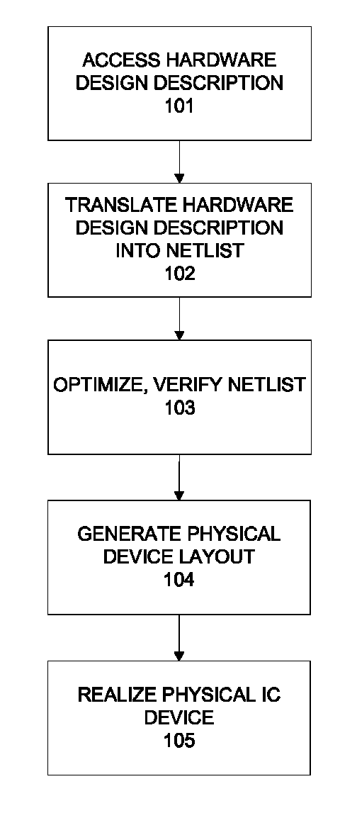
[0020]A hardware design is typically described in hardware description languages (HDLs). Such languages include, but are not limited to, Verilog, SystemVerilog, VHDL, SystemC, etc.

[0021]Suppose V is a finite set of variables {v0, . . . , vn}. Each variable represents a node in a netlist, where the netlist is a behavioral description of a hardware design. A trace over V is a sequence π=α0α1 . . . , where each αi is called a state. A state is a complete assignment of variables in V at time i. An assignment is a pair (vi,ci), where vi is a variable and ci is its corresponding value. A complete assignment of V contains one assignment for every variable in V.

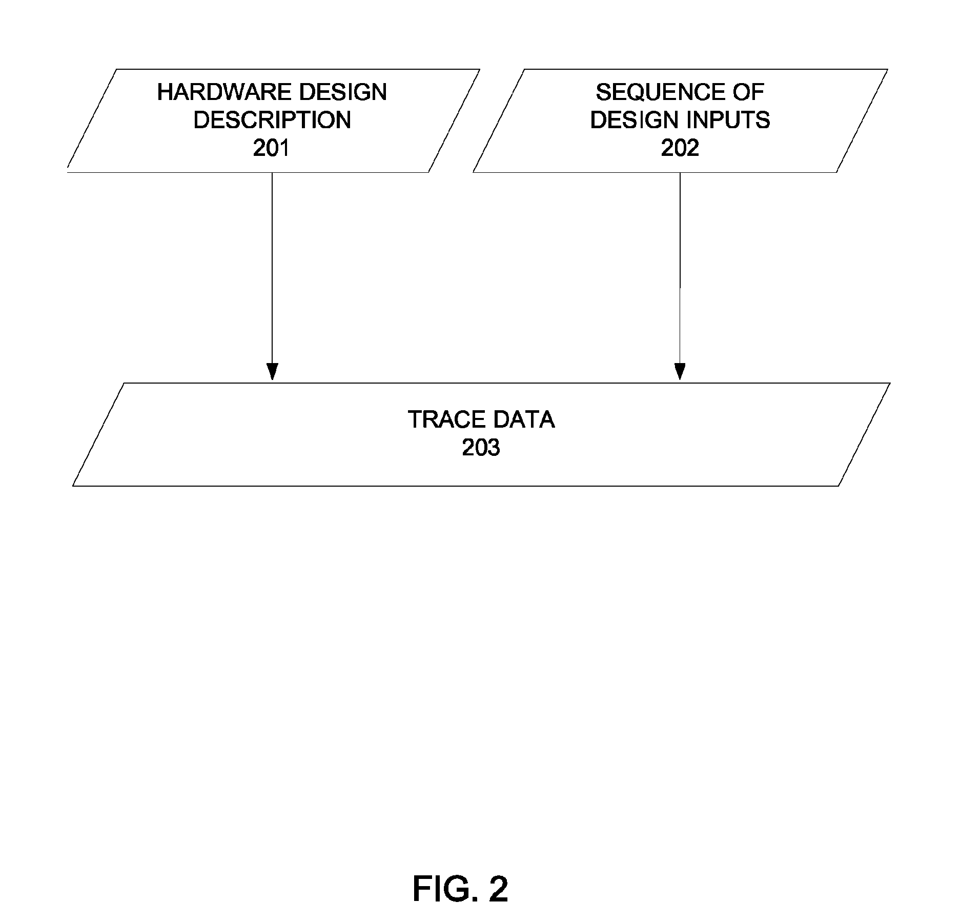
[0022]FIG. 2 illustrates a logical flow for ...


PUM


Abstract

One embodiment of the present invention provides a method that automatically generates assertions of a hardware design. The method includes accessing a trace and a set of predicates of the hardware design. Then, the trace is projected over the set of predicates to generate a second trace. Then, a new set of states of the second trace is computed and the result is represented as a logical formula. The formula is reduced by logic optimization techniques. And finally, a set of logical consequences of the logic formula is produced and each logical consequence is enumerated as an assertion.

Description

CROSS REFERENCE TO RELATED APPLICATIONS[0001]This application claims the benefit of provisional patent application Ser. No. 60 / 766,746, filed Feb. 9, 2006, which is incorporated herein by reference.BACKGROUND OF THE INVENTION[0002]1. Field of the Invention[0003]This invention relates to the design and verification of hardware systems, such as digital integrated circuits. More specifically, this invention relates to a method for generating a set of assertions of a hardware design that are true for a trace, where the trace is based on a sequence of design inputs.[0004]2. Description of the Related Art[0005]An electronic design automation (EDA) system is a form of computer aided design (CAD) system used for designing hardware systems such as integrated circuit (IC) devices. FIG. 1 illustrates a process for electronic design automation. The EDA system typically receives one or more high level behavioral descriptions of hardware design (see step 101) (e.g. in hardware description languag...

Claims


Application Information

Patent Timeline
Patent Type & Authority Patents(United States)
IPC IPC(8): G06F17/50
CPCG06F17/5045G06F30/30
Inventor LU, YUANZHU, YUNSHAN
Owner SYNOPSYS INC
Why Eureka
Try Eureka