Eureka AIR delivers breakthrough ideas for toughest innovation challenges, trusted by R&D personnel around the world.

Diesel particulate filter and exhaust emission control system

a technology of particulate filter and exhaust, which is applied in the direction of machines/engines, metal/metal-oxide/metal-hydroxide catalysts, etc., can solve the problems of difficult to raise the exhaust gas temperature, lower fuel economy or dpf, and low temperature of diesel engine exhaust gas, etc., to achieve the effect of lowering the pm combustion start temperatur

Inactive Publication Date: 2011-04-12
DOWA ELECTRONICS MATERIALS CO LTD
View PDF41 Cites 12 Cited by
  • Summary
  • Abstract
  • Description
  • Claims
  • Application Information

AI Technical Summary

Benefits of technology

[0011]The present invention has been created in view of the above problems, and it is an object of the present invention to provide a diesel particulate filter and exhaust emission control system which can lower the PM combustion start temperature than conventional ones.

Problems solved by technology

Temperature of diesel engine exhaust gas is generally low and it is difficult to raise exhaust gas temperature to the temperature to combust PM accumulated in DPF for regeneration during normal operation.
However, forcibly raising exhaust gas temperature by fuel injection may lower fuel economy or deteriorate DPF (primarily, deterioration of a carrier (filter proper) which supports catalyst) by increasing thermal load to DPF.
However, material such as SiC, etc. is generally expensive and contributes to increased cost.
However, these previous-step and subsequent-step oxidation catalysts contribute to high cost, also.
HEI6-29542 does not provide satisfactory performance and continuous regeneration of DPF has not yet been achieved.
However, alkali is highly reactive to Si which is frequently contained in the material for DPF filter proper and in the event that alkali is used for DPF catalyst, alkali may degrade the DPF proper.

Method used


Image

  • Diesel particulate filter and exhaust emission control system
  • Diesel particulate filter and exhaust emission control system
  • Diesel particulate filter and exhaust emission control system

Examples


example

[0073]Now, showing examples, the present invention will be explained specifically but the present invention is not limited by the following embodiment but may be arbitrarily modified and put into effect without departing from the spirit of the invention.

examples 1 through 7

and Comparison Example 1 through 4

[0074]The perovskite type complex oxides were fabricated as follows.

[0075]Based on the fabrication method stipulated in Japanese Patent Application Laid-Open No. 2005-187311, particles were fabricated. For raw materials, lanthanum nitrate La(NO3)3.6H2O, barium nitrate Ba(NO3)2, iron nitrate Fe(NO3)3.9H2O, are mixed in such a manner that the mol ratio of La to Ba to Fe becomes (1-x):x:1. x was varied in the range from 0 to 1. By mixing this material salt solution with a neutralizing agent, a coprecipitate was obtained. After filtering this, the filtrate was washed with water and dried at 110° C. The powder obtained is called the precursor powder.

[0076]Then, this precursor powder is fabricated by firing after heat-treating at 800° C. for 2 hours under the atmospheric environment.

[0077]Each powder of perovskite type complex oxides after firing was mixed with simulated PM. For the simulated PM, carbon black (mean particle size: 2.09 μm) available from M...

example 8

[0082]La0.8Ba0.2FeO3 which is a perovskite type complex oxide and the simulated PM were weighed to achieve the 6-to-1 mass ratio and 8.5 mg of the powder mixture was heated at 20° C. / min in the air atmosphere using a thermobalance and the combustion start temperature was obtained. FIG. 9 shows the results.


PUM

PropertyMeasurementUnit
pore diameteraaaaaaaaaa
particle sizeaaaaaaaaaa

Abstract

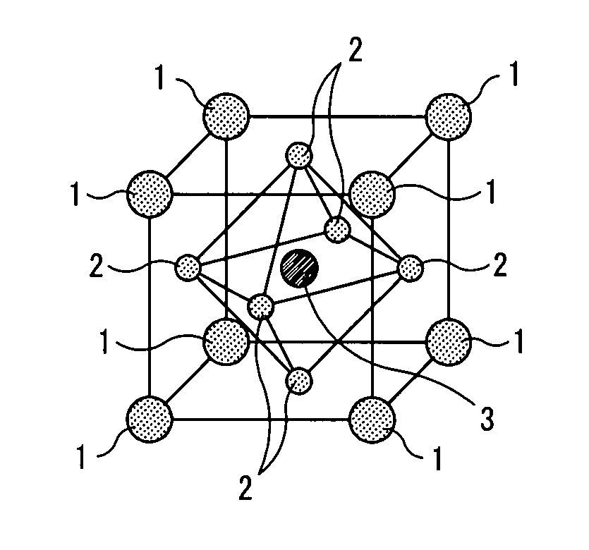
Diesel particulate filter that can lower the particulate matter (PM) combustion start temperature and use material containing silicon (Si) for a carrier. The carrier, which has a filter function, is allowed to support a perovskite-type complex oxide expressed by formula (1) as follows, wherein 0<x<0.7 and 0≦y≦1: formula (1)=La1-xBaxMnyFe1-yO3.

Description

BACKGROUND OF THE INVENTION[0001]1. Field of the Invention[0002]The present invention relates to a diesel particulate filter and an exhaust emission control system for purifying particulate matter (PM) contained in exhaust gas of diesel engines.[0003]2. Description of the Related Art[0004]In diesel engines, particulate matter (hereinafter arbitrarily called “PM”) primarily containing carbon particles exists in the exhaust gas (emission). Conventionally, in order to remove this PM, to diesel engines, a filter (diesel particulate filter, hereinafter arbitrarily called “DPF”) is installed to the exhaust mechanism and PM is collected by DPF. In addition, in order to meet lowering of DPF functions, the accumulation rate of PM collected in DPF is estimated from exhaust pressure loss and operating history, and periodical combustion purification (DPF regeneration) was carried out or periodical filter replacement was conducted.[0005]However, in the case of regenerating DPF by combusting PM a...

Claims


Application Information

Patent Timeline
Patent Type & Authority Patents(United States)
IPC IPC(8): B01J23/00B01D50/00B01J21/00
CPCB01D53/944F01N13/0097B01J23/002B01J23/8892B01J23/8986B01J35/04C01G45/1264C01G49/009C04B35/016C04B35/2641C04B35/6261F01N3/0222F01N3/035B01D53/945B01D2255/2042B01D2255/2073B01D2255/20738B01D2255/402B01D2258/012B01J2523/00C01P2002/34C01P2002/77C01P2006/12C01P2006/16C04B2235/3215C04B2235/3227C04B2235/443C04B2235/5409C04B2235/5436C04B2235/6562C04B2235/768F01N3/0253F01N2330/06F02B37/00Y02T10/22B01J2523/25B01J2523/3706B01J2523/72B01J2523/842Y02T10/12
Inventor TAKAHASHI, MASASHITANADA, HIROSHIYANO, TAKUYA
Owner DOWA ELECTRONICS MATERIALS CO LTD
Why Eureka
Eureka Blog
Learn More