
Estimating the location of a wireless terminal based on the traits of the multipath components of a signal

a wireless terminal and multipath technology, applied in the field of telecommunications, can solve the problems of high cost, high accuracy, and inability of interested parties to readily ascertain the location,

Inactive Publication Date: 2011-03-01
POLARIS WIRELESS
View PDF55 Cites 60 Cited by
  • Summary
  • Abstract
  • Description
  • Claims
  • Application Information

AI Technical Summary

Benefits of technology

The present invention is a system that can estimate the location of a wireless device without the limitations and costs of previous methods. It uses traits of electromagnetic signals that are influenced by factors like topography and the receiver. By measuring the difference in the timing of signals and analyzing them, the system can accurately determine the location of a wireless device. This technology can be used to improve the accuracy of location tracking for wireless devices.

Problems solved by technology

On the other hand, the salient disadvantage of wireless telecommunications lies in that fact that because the user is mobile, an interested party might not be able to readily ascertain the location of the user.
The first technique is only accurate (in present cellular systems), however, to within a few kilometers, and, therefore, it is generally not acceptable for applications (e.g., emergency services dispatch, etc.) that require higher accuracy.
The disadvantage of this second technique, however, is that it generally requires that hardware be added to the telecommunication system's base stations, which can be prohibitively expensive.
This technique is typically accurate to within tens of meters but is disadvantageous in that it does not work consistently well indoors, in heavily wooded forests, or in urban canyons.
Furthermore, the accuracy of this third technique can be severely degraded by multipath reflections.

Method used


Image

  • Estimating the location of a wireless terminal based on the traits of the multipath components of a signal
  • Estimating the location of a wireless terminal based on the traits of the multipath components of a signal
  • Estimating the location of a wireless terminal based on the traits of the multipath components of a signal

Examples


Embodiment Construction

[0035]For the purposes of this specification, the following terms and their inflected forms are defined as follows:[0036]The term “location” is defined as a one-dimensional point, a two-dimensional area, or a three-dimensional volume.[0037]The term “staying probability” is defined as an estimate of the probability PS(b, T, N, W) that wireless terminal W in location b at calendrical time T will still be in location b at time T+Δt, given environmental conditions, N.[0038]The term “moving probability” is defined as an estimate of the probability PM(b, T, N, W, c) that wireless terminal W in location b at calendrical time T will be in adjacent location c at time T+Δt, given environmental conditions, N.[0039]The term “environmental conditions N,” are defined to include one or more physical aspects of the environment, and includes, but is not limited to, the weather, the astronomical conditions, atmospheric conditions, the quantity and density of radio traffic, the quantity and density of...


PUM


Abstract

A technique for estimating the location of a wireless terminal at an unknown location in a geographic region is disclosed. The technique is based on the recognition that there are traits of electromagnetic signals that are dependent on topography, the receiver, the location of the transmitter, and other factors. For example, if a particular radio station is known to be received strongly at a first location and weakly at a second location, and a given wireless terminal at an unknown location is receiving the radio station weakly, it is more likely that the wireless terminal is at the second location than at the first location.

Description

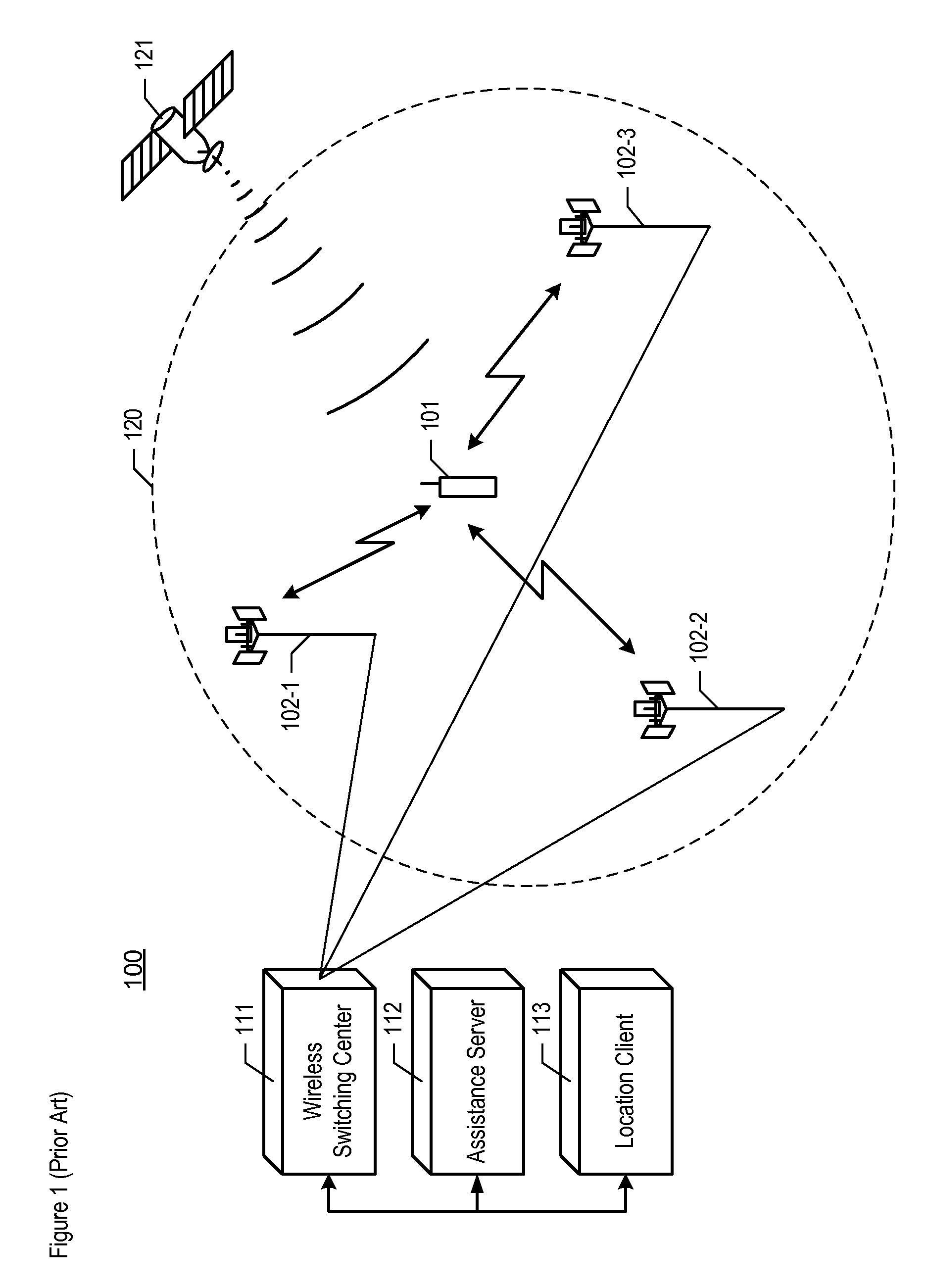
FIELD OF THE INVENTION[0001]The present invention relates to telecommunications in general, and, more particularly, to a technique for estimating the location of a wireless terminal and using the estimate of the location in a location-based application.BACKGROUND[0002]FIG. 1 depicts a diagram of the salient components of wireless telecommunications system 100 in accordance with the prior art. Wireless telecommunications system 100 comprises: wireless terminal 101, base stations 102-1, 102-2, and 102-3, wireless switching center 111, assistance server 112, location client 113, and Global Positioning System (“GPS”) constellation 121. Wireless telecommunications system 100 provides wireless telecommunications service to all of geographic region 120, in well-known fashion.[0003]The salient advantage of wireless telecommunications over wireline telecommunications is the mobility that is afforded to the users. On the other hand, the salient disadvantage of wireless telecommunications lies...

Claims


Application Information

Patent Timeline
Patent Type & Authority Patents(United States)
IPC IPC(8): H04W24/00H04W64/00
CPCG01S5/0252G01S19/22G01S19/25G01S19/42H04W64/00G01S5/0273G01S5/02521
Inventor FEUERSTEIN, MARTINGORDON, SCOT DOUGLASSPAIN, JR., DAVID STEVENSON
Owner POLARIS WIRELESS
Learn More