Transmission shaft joint design
a technology of transmission shaft and joint, which is applied in the direction of shafts, couplings, non-disconnectible pipe joints, etc., to achieve the effect of enhancing joint stability
- Summary
- Abstract
- Description
- Claims
- Application Information
AI Technical Summary
Benefits of technology
Problems solved by technology
Method used
Image
Examples
Embodiment Construction
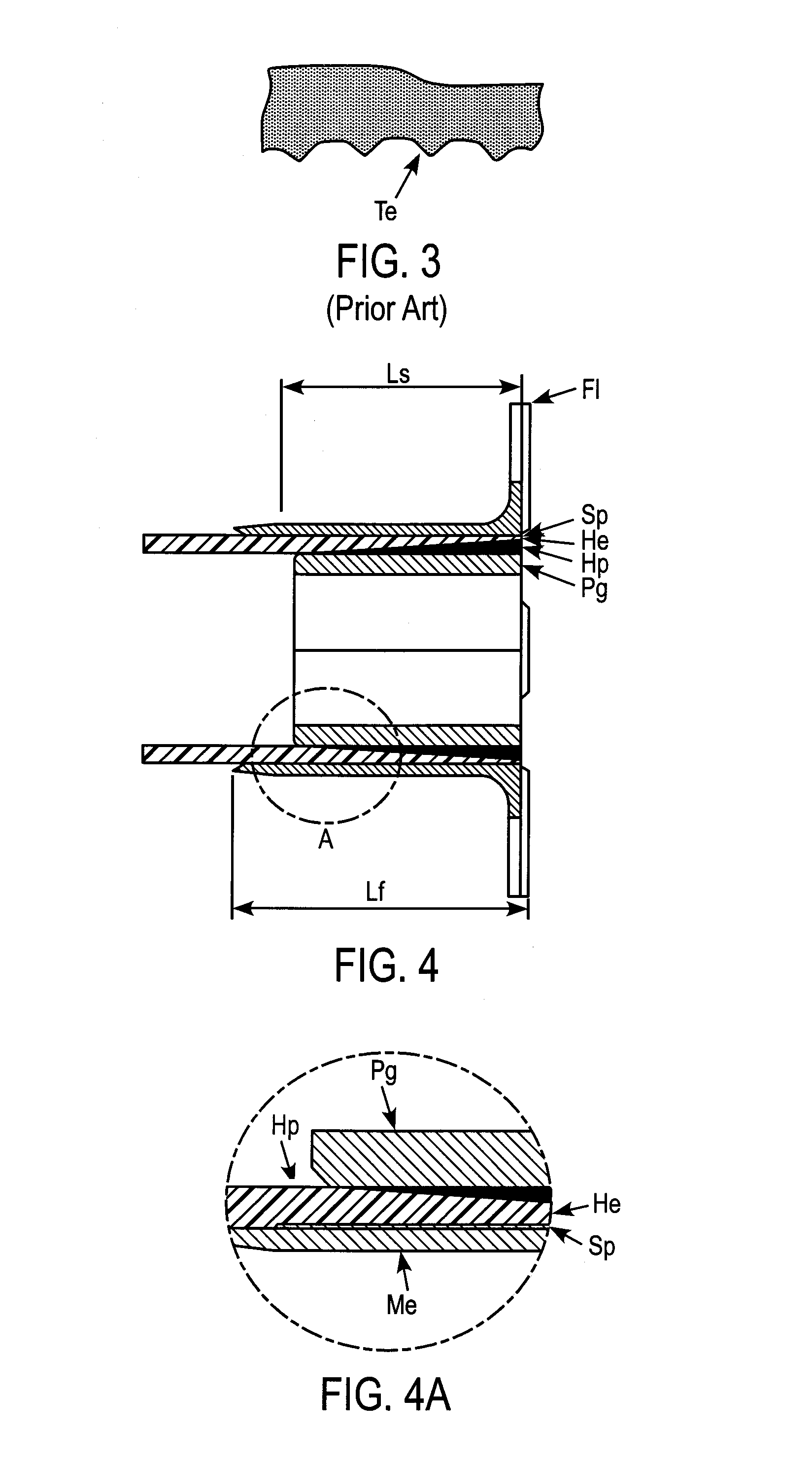
[0022]FIG. 1 shows a longitudinal section of a general internally splined metallic end coupling. The fitting is machined out of a hard, stiff and strong alloy such as corrosion resisting S143 alloy steel. The fittings consist of an internal circumferential splined region (Sp) of length Ls, a cylindrical unsplined region (Sa) of length La having a flared internal tip diameter, a flange region (F1) containing a number of bolt holes (Bh), distributed evenly around a common pitch circle diameter, through which torque can be transmitted into and out of the shaft.
[0023]FIG. 2a shows a transverse section of an internally splined metallic end coupling of the present invention, showing a flange design with six boltholes (Bh); however, any number of holes may be used depending on the stresses to be transmitted and the dimensions of the composite shaft. The transverse spline profile defined as design 2 is shown more clearly in FIG. 2b, which is an enlargement of the part of FIG. 2a which is la...
PUM
| Property | Measurement | Unit |
|---|---|---|
| Diameter | aaaaa | aaaaa |
| Bond | aaaaa | aaaaa |
Abstract
Description
Claims
Application Information
 - R&D
- Intellectual Property
- Life Sciences
- Materials
- Tech Scout
- Unparalleled Data Quality
- Higher Quality Content
- 60% Fewer Hallucinations
Browse by: Latest US Patents, China's latest patents, Technical Efficacy Thesaurus, Application Domain, Technology Topic, Popular Technical Reports.
© 2025 PatSnap. All rights reserved.Legal|Privacy policy|Modern Slavery Act Transparency Statement|Sitemap|About US| Contact US: help@patsnap.com


