
Solar cell structure, method for manufacturing same, and solar cell module

A technology of solar cells and manufacturing methods, applied in the direction of final product manufacturing, sustainable manufacturing/processing, circuits, etc., capable of solving problems such as the decline in output power of solar cells 100 and the inability to transmit current smoothly

Inactive Publication Date: 2015-09-30
MOTECH INDUSTRIES
View PDF6 Cites 2 Cited by
  • Summary
  • Abstract
  • Description
  • Claims
  • Application Information

AI Technical Summary

Problems solved by technology

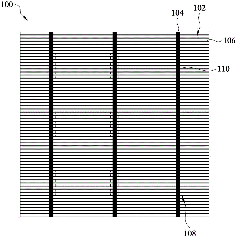
Due to the damage of the finger electrodes 106, these finger electrodes 106 cannot be effectively connected with the bus electrodes 104, thus causing the current collected by the finger electrodes 106 to fail to be transferred smoothly and collected to the bus electrodes 104, thereby causing the output power of the solar cell 100 to be reduced. decline

Method used


Image

  • Solar cell structure, method for manufacturing same, and solar cell module
  • Solar cell structure, method for manufacturing same, and solar cell module
  • Solar cell structure, method for manufacturing same, and solar cell module

Examples


Embodiment Construction

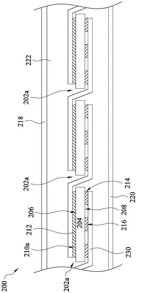
[0031] Please refer to figure 2 , which is a schematic cross-sectional view illustrating a solar cell module according to an embodiment of the present invention. In this embodiment, the solar cell module 200 mainly includes an upper plate 218 , a lower plate 220 , several solar cell structures 202 a , several connecting strips 230 , and one or more packaging material layers 222 .

[0032]In some embodiments, the upper plate 218 is a transparent plate, such as glass. The lower sheet 220 can also be called a back sheet, and the lower sheet 220 can be a white opaque sheet. The solar cell structure 202 a is disposed between the upper plate 218 and the lower plate 220 . The connection strips 230 are also located between the upper plates 218 and 220 , and two ends of each connection strip 230 can be respectively connected to the two adjacent solar cell structures 202 a to electrically connect the two solar cell structures 202 a. The connection strip 230 can also be called a weld...


PUM


Abstract

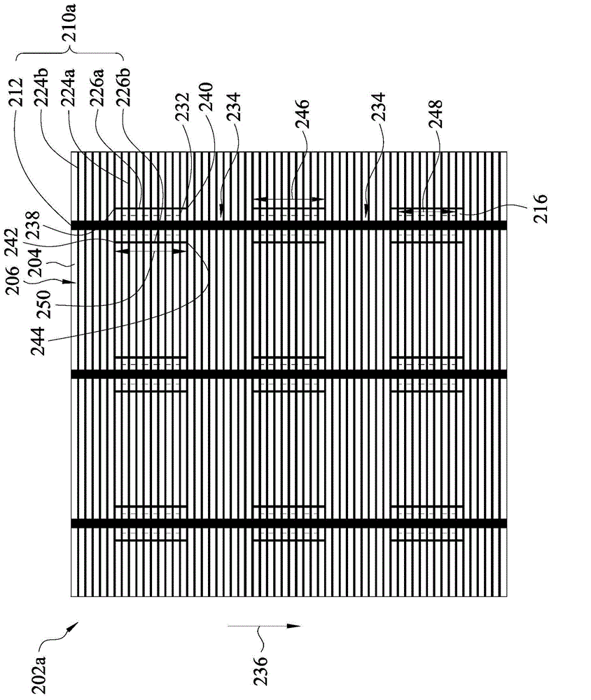
The invention discloses a solar cell structure, a method for manufacturing the same, and a solar cell module. The solar cell structure comprises a substrate, a first electrode and a second electrode. The first electrode is arranged on the first surface of the substrate, and comprises at least one first bus electrode, multiple finger electrodes and multiple first auxiliary electrodes. The first bus electrode intersects with the finger electrodes, and does not intersect with the first auxiliary electrodes. The second electrode is arranged on the second surface of the substrate, and comprises at least one second bus electrode. The second bus electrode comprises multiple electrode parts corresponding to the first auxiliary electrodes. The electrode parts are arranged at intervals, and the orthographic projection of the electrode parts on the first surface overlaps with the first bus electrode. The finger electrodes comprise multiple first finger electrode units intersecting with the orthographic projection of the electrode parts. Each first auxiliary electrode is arranged beside one side of the orthographic projection of the corresponding electrode part, and intersects with the first finger electrode units.

Description

technical field [0001] The present invention relates to a photoelectric conversion device, and in particular to a solar cell structure and a manufacturing method thereof. Background technique [0002] After the solar cell module is manufactured, it is usually required to conduct a reliability test to ensure that the solar cell module produced can pass the international certification and the specification required by the customer. Generally speaking, the reliability tests of solar cell modules mainly include visual inspection, insulation test, low-light performance test, outdoor exposure test, hot spot durability test, ultraviolet test, thermal cycling test, humidity Humidity freeze test, damp heat test, lead terminal test, wet leakage current test, mechanical load test, hail test and light attenuation test, etc. [0003] However, after the thermal cycle test, the fill factor of the solar cell module often decreases, resulting in a decrease in the maximum output power. Plea...

Claims


Application Information

Patent Timeline
IPC IPC(8): H01L31/042H01L31/0224H01L31/18
CPCY02E10/50Y02P70/50
Inventor 锺文泰陈建文王博文
Owner MOTECH INDUSTRIES
Learn More