
Host identity protocol method and apparatus

a protocol and host technology, applied in the field of host identity protocol methods and apparatuses, can solve the problems of increasing the complexity of the situation, affecting the security of the system, and the immobility of the computer,

Inactive Publication Date: 2011-01-18
TELEFON AB LM ERICSSON (PUBL)
View PDF13 Cites 6 Cited by
  • Summary
  • Abstract
  • Description
  • Claims
  • Application Information

AI Technical Summary

Benefits of technology

HIP enables secure and seamless communication by separating identity and location functions, allowing hosts to maintain connections while changing locations and using multiple paths, thereby enhancing security and mobility management across various network environments.

Problems solved by technology

There was little need to consider techniques for dealing with host mobility since computers were relatively bulky and immobile.
However, experience has shown that it is fairly hard to reach combined security and mobility using the current standards.
When mobility is also considered, the situation becomes even more complicated: since IP addresses act as host identifiers in this scheme, they must not be changed; however, since IP addresses also describe topological locations, they must necessarily change when a host changes its location in the network.
Clearly, it is impossible to achieve both stability and dynamic changes at the same time.
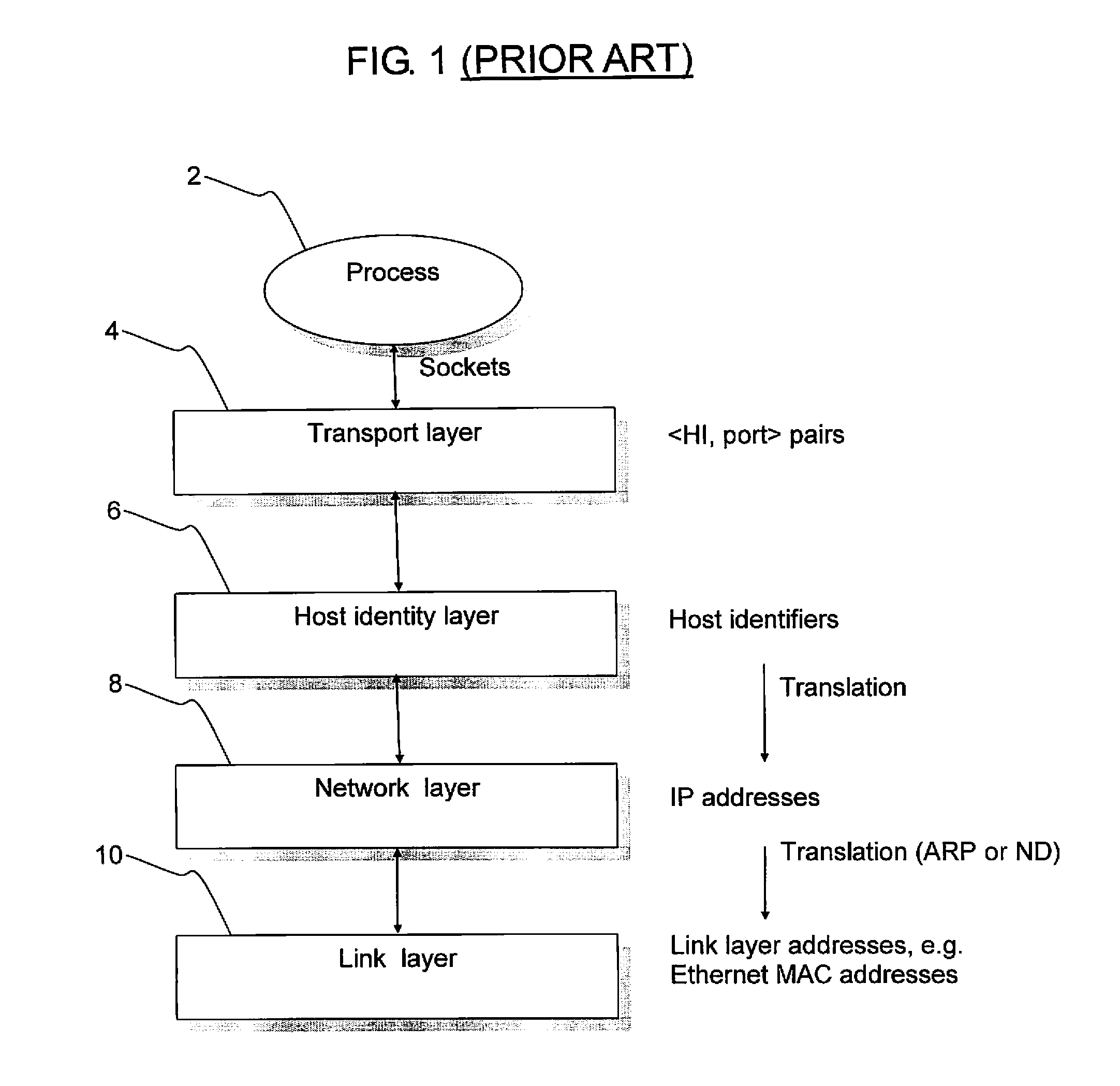
The HIP Host Identity (HI), being a public key, can be quite long and is therefore not practical in all situations.
If, for some reason, the packet is routed to a wrong destination, the receiver is not able to open the packet as it does not have the correct key.
The DNS system is too slow to be used for constantly changing location information.
False, or non-routable, addresses in the REA packet may be caused either because the HMN is a malicious node, it has an error in the stack implementation, or the HMN may be inside a network that uses private addresses that are not routable in the Internet.

Method used


Image

  • Host identity protocol method and apparatus
  • Host identity protocol method and apparatus
  • Host identity protocol method and apparatus

Examples


Embodiment Construction

[0082]Embodiments of the present invention will be described within the framework of the GPRS / UMTS network architecture shown in FIG. 6. The principles underlying an embodiment of the present invention are equally applicable to UMTS as they are to GPRS.

[0083]As mentioned above, GPRS has been designed as an extension to the existing GSM network infrastructure, with the aim of providing a connectionless packet data service. GPRS introduces a number of new functional elements over GSM that support the end-to-end transport of IP-based packet data, as will be described below.

[0084]The communications system 100 shown in FIG. 6 comprises a mobile station (MS) 102 in communication with a Base Transceiver Station (BTS) 104 which in turn communicates with a Base Station Controller (BSC) 106. The BTS 104 and BSC 106 together make up the Base Station Subsystem (BSS). At the BSC 106, a Packet Control Unit (PCU, not shown) differentiates circuit switched data destined for a telephony network 110 ...


PUM


Abstract

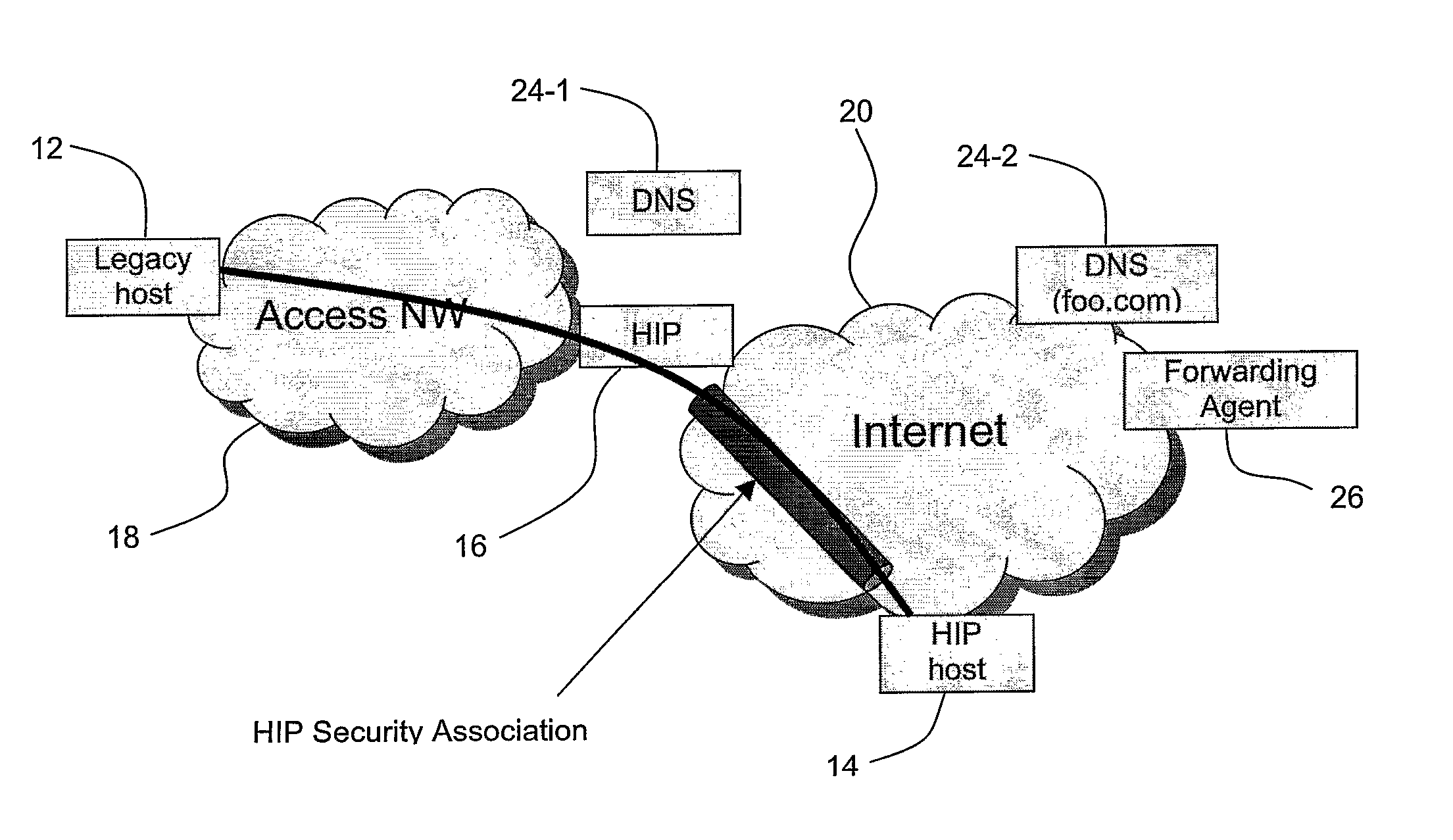
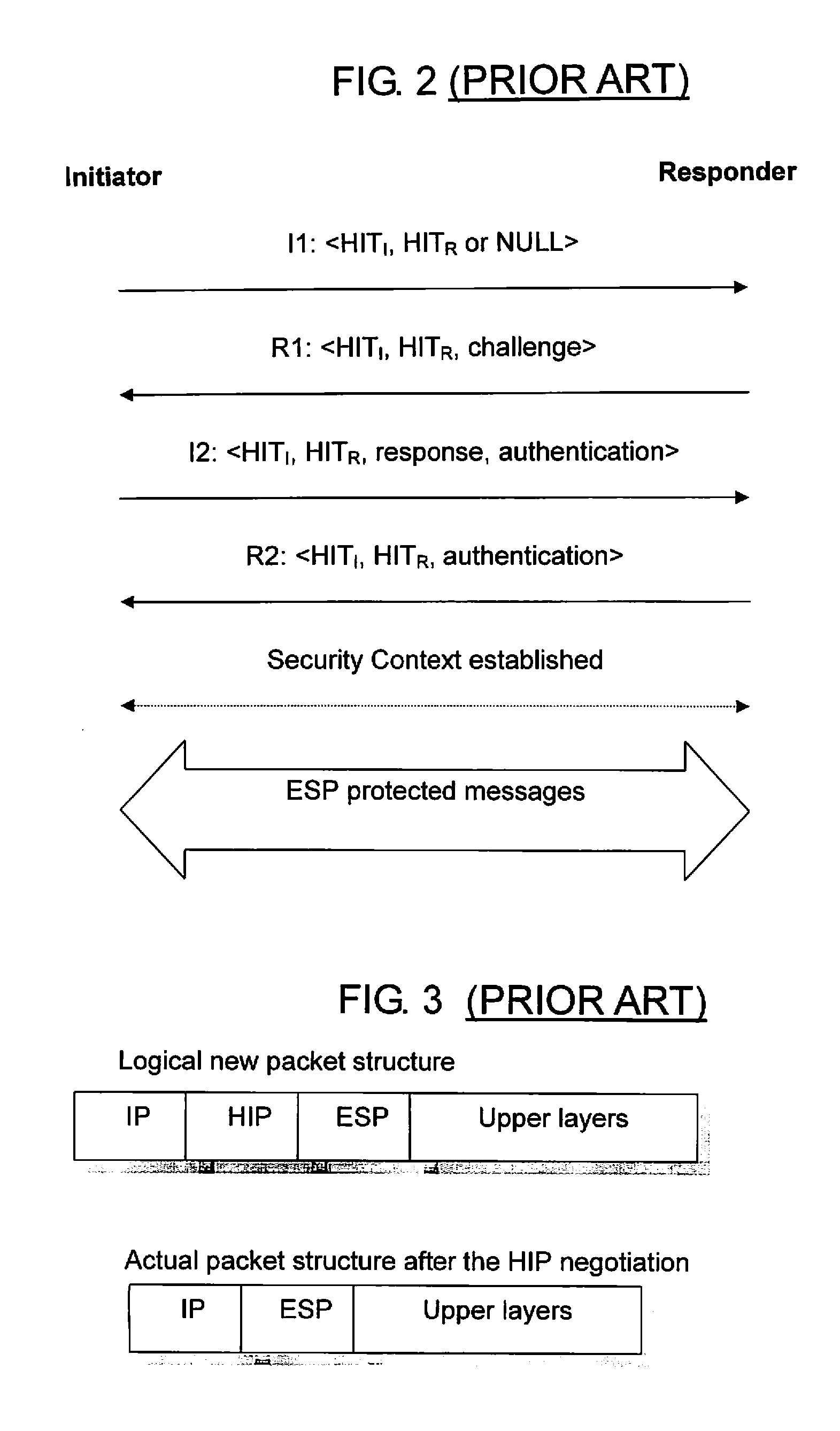
A method of using the Host Identity Protocol (HIP) to at least partially secure communications between a first host operating in a first network environment and a second, HIP-enabled, host operating in a second network environment, with a gateway node forming a gateway between the two environments. An identifier is associated with the first host, stored at the gateway node, and sent to the first host. The identifier is then used as a source address in a subsequent session initiation message sent from the first host to the gateway node, having an indication that the destination of the message is the second host. The stored identifier at the gateway node is then used to negotiate a secure HIP connection to the second host. The first network environment may be a UMTS or GPRS environment, in which case the gateway node may be a Gateway GPRS Support Node (GGSN).

Description

BACKGROUND[0001]1. Field[0002]The present invention relates to a method of using the Host Identity Protocol (HIP) to at least partially secure communications between two hosts operating in two different respective network environments, at least one of the two hosts being HIP-enabled.[0003]2. Description of Related Art[0004]When the Internet was originally devised, hosts were fixed in location and there was implicit trust between users despite the lack of real security or host identification protocols, and this situation continued even upon wider uptake and use of the technology. There was little need to consider techniques for dealing with host mobility since computers were relatively bulky and immobile.[0005]With the revolution in telecommunications and computer industry in the early 1990's, smaller communication equipment and computers became more widely available and the invention of the World Wide Web, and all the services that emerged with it, finally made the Internet attracti...

Claims


Application Information

Patent Timeline
Patent Type & Authority Patents(United States)
IPC IPC(8): H04L29/06H04L12/56H04L29/08H04L29/12
CPCH04L29/12018H04L29/12066H04L61/10H04L61/1511H04L63/08H04L63/164H04L69/329H04W8/04H04W80/04H04L69/24H04L61/4511
Inventor JOKELA, PETRINIKANDER, PEKKASALMELA, PATRIK MIKAELARKKO, JARIYLITALO, JUKKA
Owner TELEFON AB LM ERICSSON (PUBL)
Learn More