
Disk drive device

a technology of a drive and a mounting surface, which is applied in the direction of recording information storage, record carrier contruction details, instruments, etc., can solve the problems of large disturbance, large turbulence buffeting of magnetic disks and hgas, and complex and difficult rapid and accurate positioning control, etc., to improve joint reliability, increase the width of the feedthrough mounting surface 252, and reduce thermal stress

Active Publication Date: 2011-01-18
WESTERN DIGITAL TECH INC
View PDF6 Cites 19 Cited by
  • Summary
  • Abstract
  • Description
  • Claims
  • Application Information

AI Technical Summary

Benefits of technology

The present invention improves the reliability of joints in a disk drive device by preventing cracks and ensuring proper contact between components. This is achieved by increasing the width of the mounting surface of the feedthrough at areas with relatively large thermal stress and decreasing the width at areas with relatively small thermal stress. This prevents the solder joint section from cracking and coming into contact with pins, even in cases where the temperature environment changes during use.

Problems solved by technology

These cause fluctuation of air (turbulence) to buffet the magnetic disks and HGAs.
This turbulence buffeting can be a big disturbance for positioning heads for data which are recorded with high-density on a magnetic disk.
This is because the turbulence occurs at random and it is difficult to estimate its magnitude and cycle so that swift and accurate positioning control will be complex and difficult.
Also the turbulence buffeting may cause a noise to impair the quietness of the device.
Another problem caused by influence of the air within the device due to the high-speed rotation other than the foregoing is increase of electric power consumption.
This is called a windage loss, which becomes larger as the disk rotates at higher speed.
However, molecules of helium are so small and a diffusion coefficient of helium is large.
Therefore, there has been a problem that enclosures used for usual HDDs are poorly sealed so that helium gas leaks easily during normal use.
Furthermore, in solder-joining the feedthrough and the base, it is important to consider a problem that the overflowed solder contacts the pins to cause a short, and the like.

Method used


Image

  • Disk drive device
  • Disk drive device
  • Disk drive device

Examples


Embodiment Construction

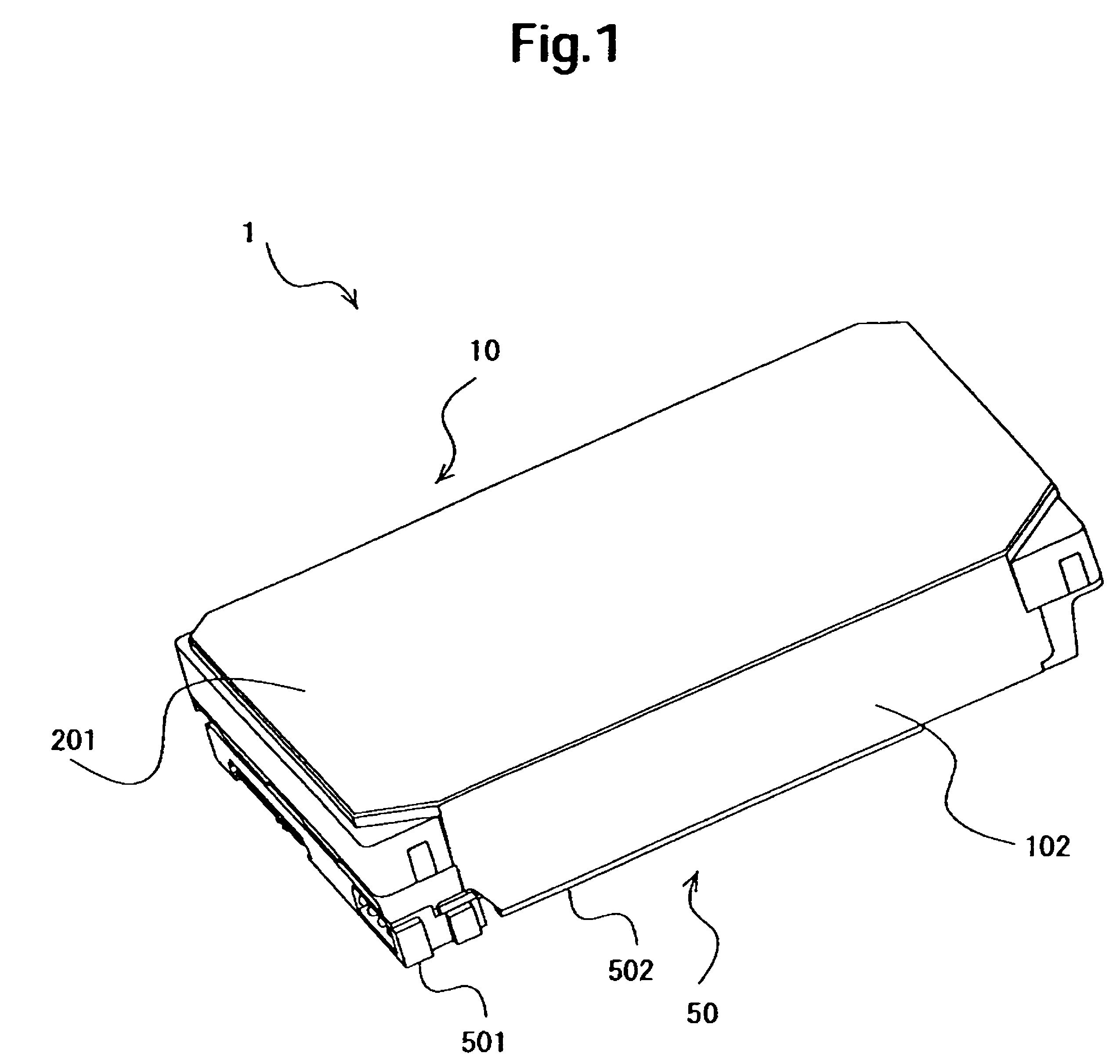
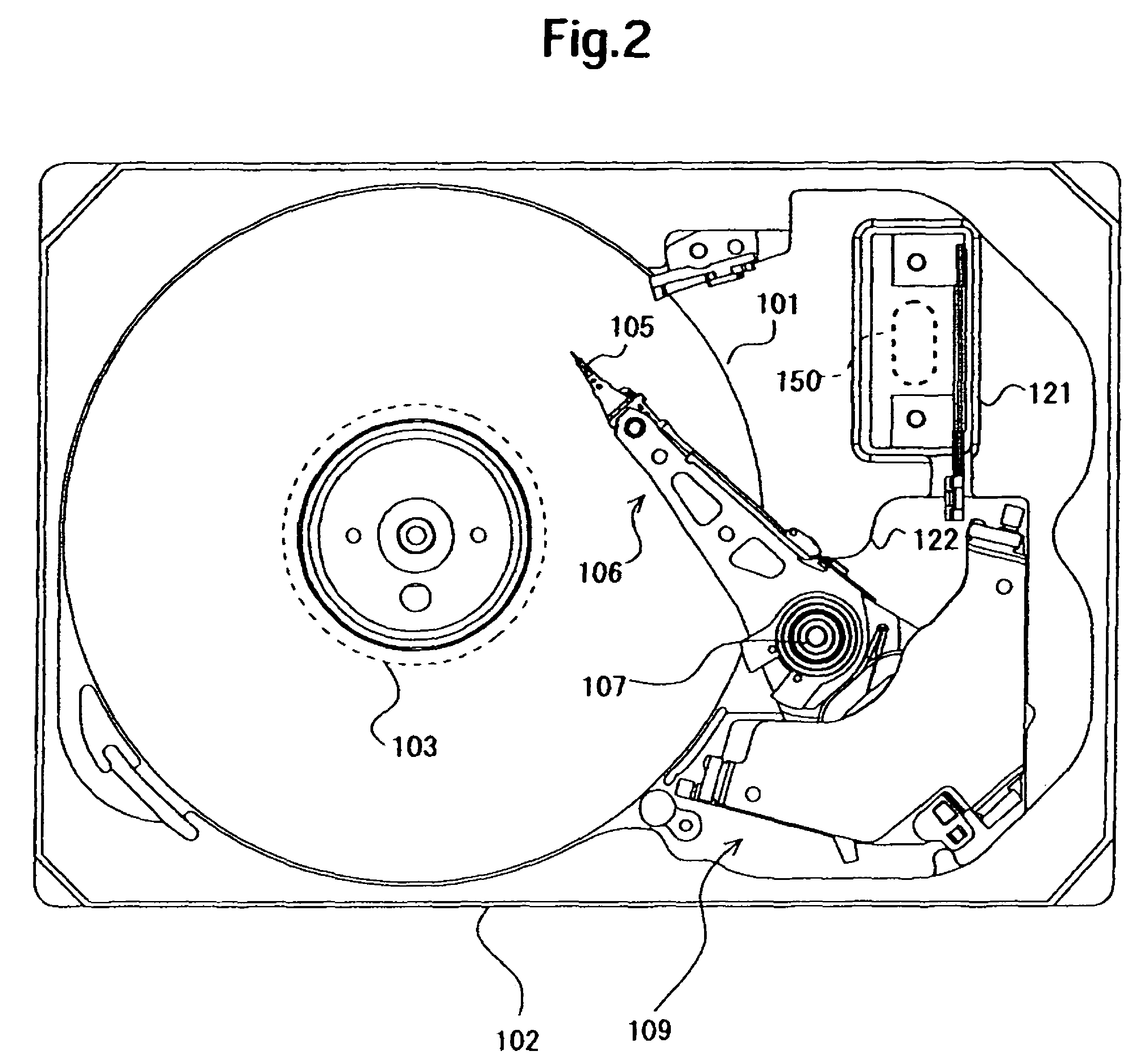
[0019]Embodiments of the present invention relate to a disk drive device, more particularly to a hermetically-sealed disk drive device suitable for enclosing low-density gas, such as helium gas, within the device.

[0020]A disk drive device according an aspect of embodiments of the present invention comprises a disk, a motor for rotating the disk, a head for accessing the disk, a moving mechanism for supporting and moving the head, a base for housing the disk, the motor, the head and the moving mechanism, a cover joined to the base. Gas with lower density than air is sealed within an interior space which is formed by joining the base and the cover. The disk drive further comprises a feedthrough which is solder jointed to the base to cover an opening penetrating the base to join an outside of the device and the interior space and is connected electrically to a wiring arranged in the interior space. The base has a mounting surface on which the feedthrough is mounted around the opening. ...


PUM

PropertyMeasurementUnit
thickness W1aaaaaaaaaa
thickness W2aaaaaaaaaa
densityaaaaaaaaaa

Abstract

In a disk drive device in which low-density gas is sealed, embodiments of the present invention help to improve joint reliability at a solder joint section between a feedthrough and an enclosure with respect to stress applied by deformation due to changes in temperature environment in use. According to one embodiment, helium gas is sealed in an interior space of an HDD. A feedthrough is solder jointed to a feedthrough mounting surface of a base. At a part with relatively large thermal stress, a width of the feedthrough mounting surface is increased, and at a part with relatively small thermal stress, a width of the feedthrough mounting surface is decreased. This prevents a crack penetrating path from being generated at the solder joint section due to the thermal stress and prevents the solder joint section from contacting pins.

Description

CROSS-REFERENCE TO RELATED APPLICATION[0001]The instant nonprovisional patent application claims priority to Japanese Patent Application No. 2007-001819 filed Jan. 9, 2007 and which is incorporated by reference in its entirety herein for all purposes.BACKGROUND OF THE INVENTION[0002]Currently, hard disk drives (hereinbelow, referred to as HDDs) rotate magnetic disks and drive head gimbal assemblies (hereinbelow, referred to as HGAs) at high speed in response to requests for huge capacity, high recording density, and high-speed accessing. These cause fluctuation of air (turbulence) to buffet the magnetic disks and HGAs. This turbulence buffeting can be a big disturbance for positioning heads for data which are recorded with high-density on a magnetic disk. This is because the turbulence occurs at random and it is difficult to estimate its magnitude and cycle so that swift and accurate positioning control will be complex and difficult. Also the turbulence buffeting may cause a noise t...

Claims


Application Information

Patent Timeline
Patent Type & Authority Patents(United States)
IPC IPC(8): G11B33/14
CPCG11B25/043G11B33/122G11B33/1466
Inventor SHINDO, HITOSHINAKAMIYA, TERUHIROUEFUME, KOUKIHAYAKAWA, TAKAKO
Owner WESTERN DIGITAL TECH INC
Learn More