
Delay unit for door with a door closer, door closer with a delay unit, and door with a door closer having a delay unit

a technology of delay unit and door closer, which is applied in the direction of motor/generator/converter stopper, dynamo-electric converter control, instruments, etc., can solve the problem of difficulty in providing the delay mechanism with the door closer, and achieve the effect of compact and economical manufacturing, saving electric power, and compact and economical manufacturing

Inactive Publication Date: 2010-12-28
DT ENG
View PDF19 Cites 24 Cited by
  • Summary
  • Abstract
  • Description
  • Claims
  • Application Information

AI Technical Summary

Benefits of technology

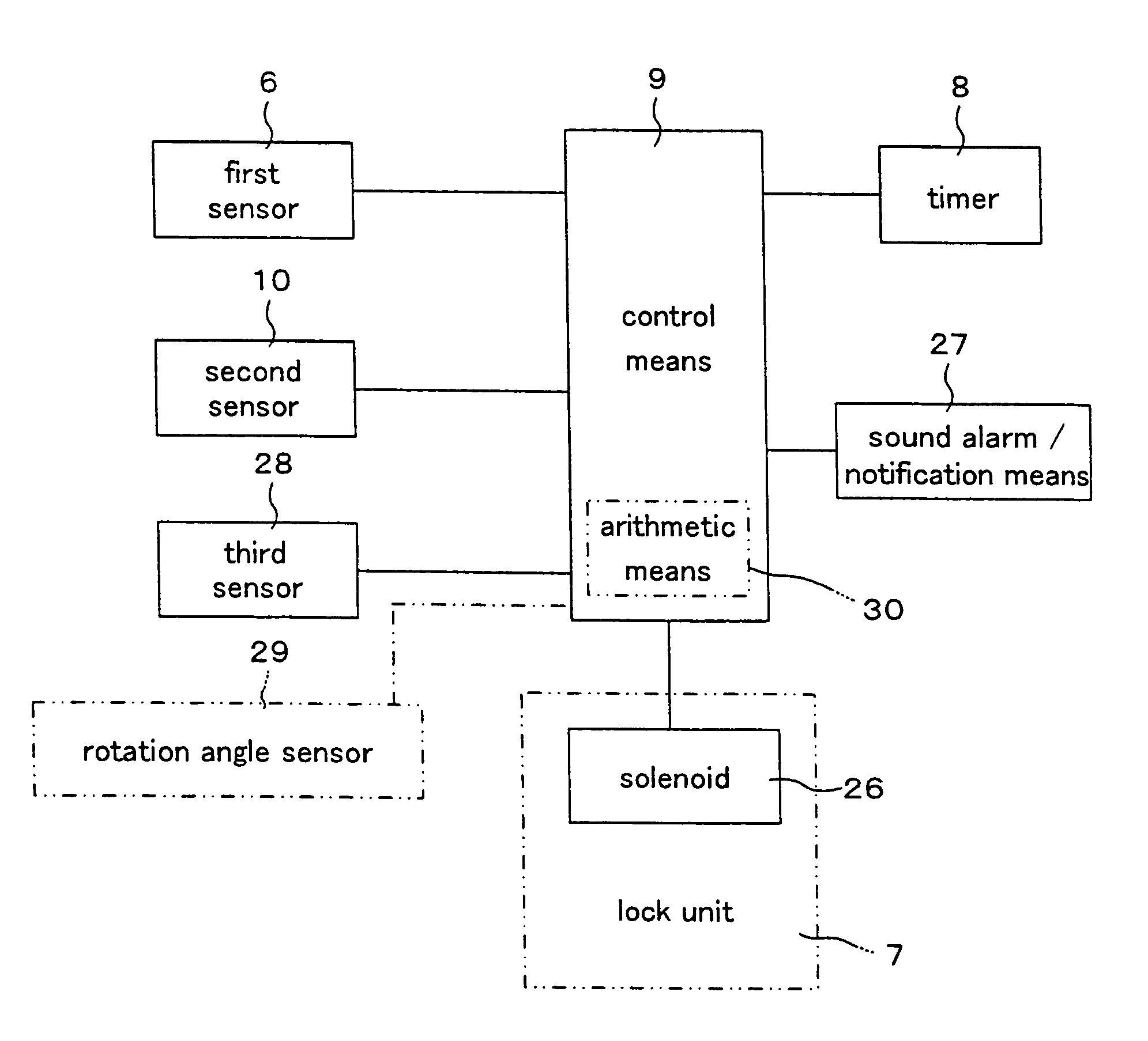
[0030]According to the present invention defined in claim 2, since a delay unit for door with a door closer comprises a second sensor for detecting the door opened to the second certain angle, wherein the second sensor is connected with the control means; when the door has opened to the second certain angle, the electric lock / unlock means locks the rotation of the rotation axis of the door; and on the basis of the detection signal of the second sensor, the control means controls the timer to work, in addition to the advantage of the invention defined in claim 1, the door can be kept open, when the door has been opened to the second certain angle.
[0031]According to the present invention defined in claim 3, since a delay unit for door with a door closer comprises a rotation angle sensor for continuously detecting the rotation angle of the door, and an arithmetic means provided with the control means, wherein when the rotation angle sensor has detected the door stopped open at an angle beyond the first certain angle less than the second certain angle, the control means controls the timer to be reset and start the measurement of the time; when the timer has finished the measurement of a total delay time defined as the excess delay time added by a delay time, the first certain time, the control means sends a control signal to the electric lock / unlock means, thereby releasing the rotation lock of the rotation axis of the door by means of the electrical lock / unlock means, in addition to the advantage of the invention defined in claim 1, the delay time for starting the closing motion of the door can be extended in proportion to the time that a user holds the door open at an angle beyond the first certain angle less than the second certain angle.
[0032]According to the present invention defined in claim 4, since a delay unit for door with a door closer is arranged such that the electric lock / unlock means is tightly fixed to the rotation axis of the door, and includes a ball capable of freely engaging in a concave portion formed on the lower surface of the lock plate, a spring for pressing the ball, a lock pin capable of freely pressing the spring, and a solenoid for moving the lock pin in and out; wherein, by means of pressing the spring and the lock pin, the rotation of the lock plate is locked by pressing the ball to contact with the concave portion; by means of the energizing the solenoid, the force pressing the lock pin is released or reduced, thereby releasing the lock of the rotation of the lock plate, in addition to the advantage of the invention defined in claim 1, the electrical lock / unlock means can be fabricated compactly and economically.
[0033]According to the present invention defined in claim 5, since a delay unit for door with a door closer is arranged such that the electric lock / releasing means is tightly fixed to the rotation axis of the door, and includes a lock plate for locking the rotation of the rotation axis, a lock member laid in the housing and capable of freely engaging in the concave formed on the lower surface of the lock plate, a front spring for pressing the lock member, a lock piston capable of freely sliding inside the housing and freely pressing the front spring, a rear spring for pressing the lock piston, a movable pin for locking the slide of the lock piston by means of moving in and out inside the housing, and a solenoid for moving the movable pin in and out; wherein when the movable pin has stuck out into the housing by means of the solenoid, the sliding movement of the lock piston is locked; and when the movable pin doesn't stick out into the housing by means of the solenoid, the lock of the sliding movement of the lock piston is released, in addition to the advantage of the invention defined in claim 1, the electrical lock / unlock means can be fabricated compactly and economically and can save electric power.
[0034]According to the present invention defined in claim 6, since a delay unit for door with a door closer comprises an alarm / notification means connected with the control means, and a third sensor for detecting the closure of the door; wherein the control means controls the alarm / notification means to work on the basis of at least one signal from among signals form the first sensor, second sensor, third sensor, and timer, in addition to the advantage of the invention defined in claim 1, there is an advantage that it is possible to notify the generation of the signal from the first sensor, second sensor, third sensor, or timer by means of the alarm / notification means.
[0035]According to the present invention defined in claim 7, since a delay unit for door with a door closer is arranged such that the control means, when the rotation angle sensor has detected the door stopped open at an angle beyond the first certain angle less than the second certain angle, controls, during the door is stopped, the alarm / notification means to work at a certain time interval or notify the time at a certain time interval by means of voice, in addition to the advantage of the invention defined in claim 3, it is possible to notify the rest time of the door to a man / woman handling the door, thereby he / she can easily set the excess delay time of the door.

Problems solved by technology

However, since the aforementioned door closers both are provided the delay mechanism with them, there may be a problem in the appearance by means of providing the delay mechanism with the door closer; in other case that the door closer is embedded inside the door, wall, or the ceiling, as well as under the floor and thereby being not exposed, there may be a difficulty in providing the delay mechanism with the door closer.

Method used


Image

  • Delay unit for door with a door closer, door closer with a delay unit, and door with a door closer having a delay unit
  • Delay unit for door with a door closer, door closer with a delay unit, and door with a door closer having a delay unit
  • Delay unit for door with a door closer, door closer with a delay unit, and door with a door closer having a delay unit

Examples


first embodiment

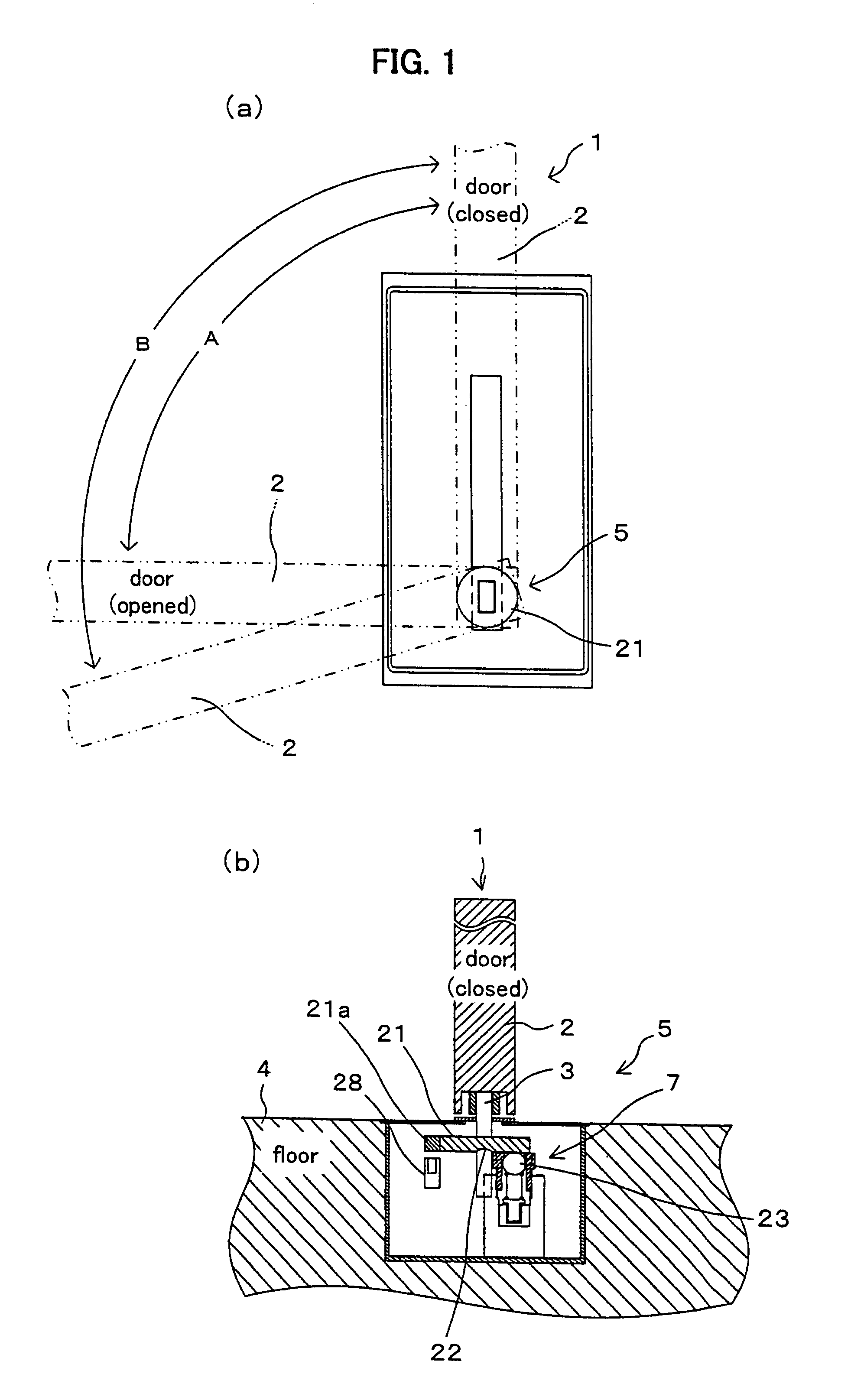
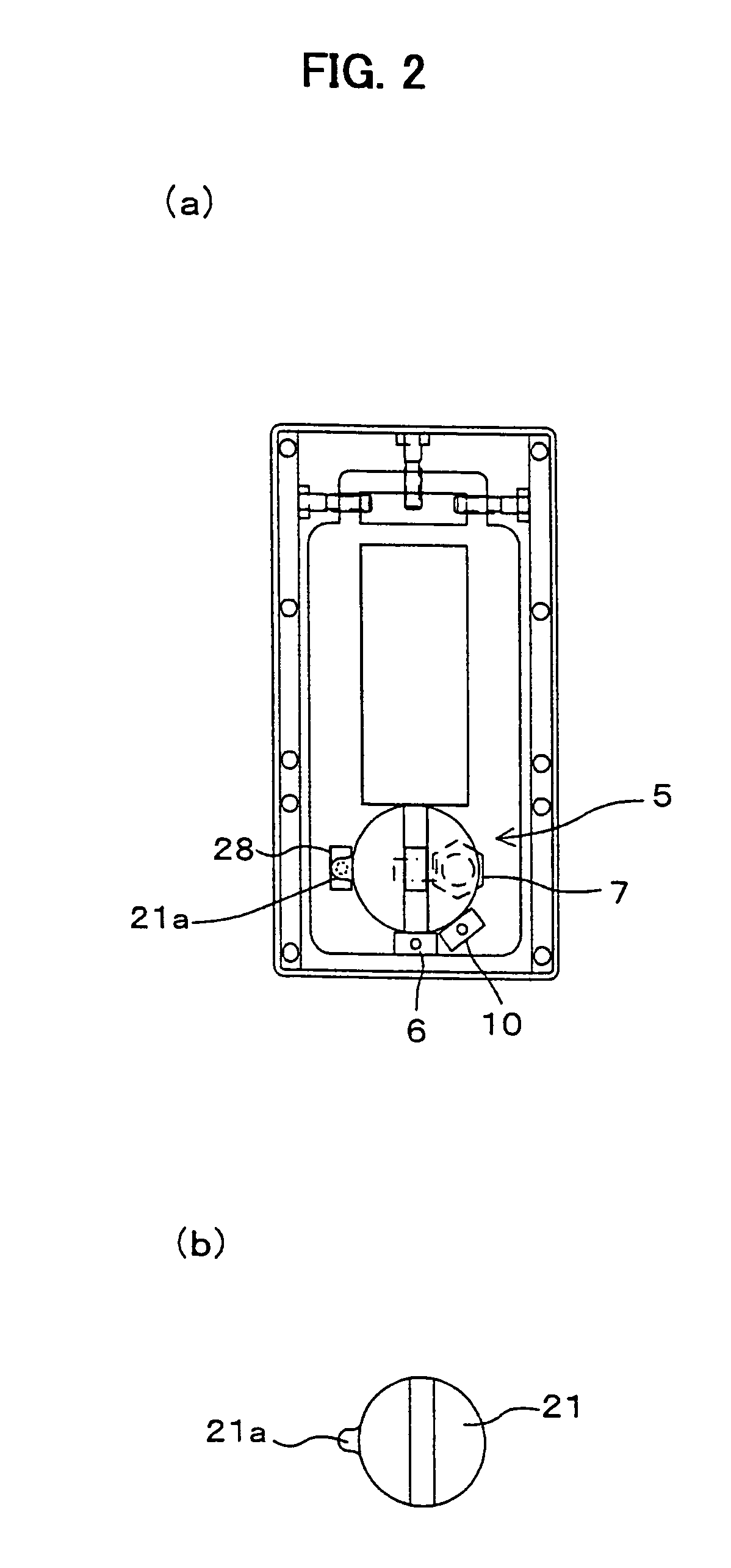
[0066]In FIGS. 1 and 2, the symbol 1 denotes a door with a door closer according to the present invention. The door with a door closer 1 comprises a door closer (not shown) for pressing the door 2 toward the closing direction, wherein a delay unit 5, which has a function for locking the rotational motion of the door 2 for a certain time (hereinafter, referred to as “first certain time”) and unlocking thereafter, is installed, connected with the rotation axis 3, around the lower part of the rotation axis 3 of the door 2 under the floor surface 4. Hereat, the place, where the delay unit 5 is installed, should not be construed as limited under the floor surface 4, but it can be inside the wall or ceiling of the building.

[0067]The delay unit 5 includes a first sensor 6 for detecting the door 2 having been opened to the first certain angle A (for example, 90 deg.) shown in FIG. 1(a), a lock unit 7 as electrical lock / unlock means for electronically locking and unlocking of the rotational ...

second embodiment

[0108]In FIG. 5, the symbol 31 denotes the door with a door closer according the present invention.

[0109]The door with a door closer 31 is arranged such that a lock unit 32, which is an electrical lock / unlock means of power saving type, is provided substitutionary for the lock unit (indicated by the symbol 7 in FIG. 1), which is an the electrical lock / unlock means of the delay unit (indicated by the symbol 5 in FIG. 1) provided to the aforementioned door with a door closer (indicated by the symbol 1 in FIG. 1).

[0110]The lock unit 32 includes: the lock plate 21, tightly fixed to the rotation axis 3 of the door 2, for locking the rotational motion of the rotation axis 3; as shown in FIG. 6, a lock member 34, laid inside a housing 33, for capable of freely engaging into the concave portion 22 formed on the lower surface of the lock plate 21; a front spring 35 for pressing the lock member 34; a lock piston 36 freely slidable inside the cylindrical hollow 33a formed in the housing 33 and...

third embodiment

[0138]In FIG. 11, the symbol 81 denotes an improved lock-unlock mechanism of the lock-unlock mechanism (indicated by the symbol 75 in FIG. 10) of the door with a door closer (indicated by the symbol 41 in FIG. 8) according to the present invention. The improved lock-unlock mechanism has a function such that the door (indicated by the symbol 2) is kept opened, when having opened to the second certain angle (for example, 110 deg.), in addition to that of the door with a door closer (indicated by the symbol 41 in FIG. 8).

[0139]The lock-unlock mechanism 81 has a structure of lock plate 49 with a lock concave portion 82 at a certain position; and the lock concave portion 82 is a concave formed on the upper surface of the lock plates 49 so as to engage with a second lock pin 83 provided differently from the lock pin 46, when the door is opened to the second certain angle. Therefore, the lock concave portion 82 is formed at the position, where the lock pin 83 locates when the door is opene...


PUM


Abstract

The Objective of the present invention is to provide a delay unit for door with a door closer, which is capable of automatically closing the door after the elapse of a certain time since the door was opened and can be installed in case that the door closer is embedded inside the building and thereby being not exposed.The objective is solved by providing a delay unit 5 for door with a door closer comprising: a first sensor for detecting the door 2 opened to the first angle A, a lock unit 7 for electrically lock / unlock of the rotation of the rotation axis 3 of the door 2, a timer, a first sensor, and a control means, with which the first sensor, lock unit 7, and timer is connected, for controlling the lock unit 7 based on the signals from the first sensor and timer.

Description

[0001]This application is a U.S. patent application claiming priority on JP 2006-67324 filed Mar. 13, 2006, and JP 2006-342363 filed Dec. 20, 2006, the entire contents of each of which are hereby incorporated herein by reference.FIELD OF THE INVENTION[0002]The present invention relates to a delay unit for door with a door closer, door closer with a delay unit, and door with a door closer having a delay unit, which can, when the door has opened, lock the movement of the door and release the lock after the elapse of a certain time, thereby automatically closing the door.BACKGROUND OF THE INVENTION[0003]As a conventional door with a door closer of this type, the applicant already disclosed it in Patent applications: Japanese Patent Application No. 2005-308456 and No. 2005-356164.[0004]In Japanese Patent Application No. 2005-308456, the door with a door closer is arranged such that by providing with a delay mechanism including such as a planetary gear unit(s), a spiral spring(s) to the ...

Claims


Application Information

Patent Timeline
Patent Type & Authority Patents(United States)
IPC IPC(8): H02P1/22
CPCE05F15/79E05F15/60E05F15/73E05Y2400/816E05F15/00E05Y2900/132E05F3/14E05F3/00
Inventor MIYASHITA, SUGAYA
Owner DT ENG
Learn More