
Water and oil mist elimination apparatus for a vehicular compressed air storage system

a technology of vehicular compressed air and elimination apparatus, which is applied in the direction of separation process, liquid degasification, filtration separation, etc., can solve the problems of no longer adsorbing moisture or regenerating

Active Publication Date: 2010-12-28
JOHNSON WELDED PRODS
View PDF14 Cites 17 Cited by
  • Summary
  • Abstract
  • Description
  • Claims
  • Application Information

AI Technical Summary

Benefits of technology

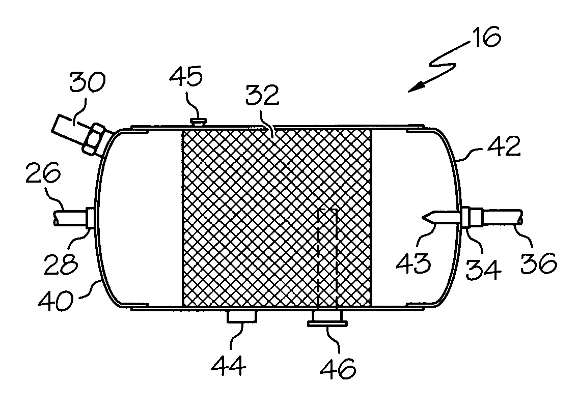
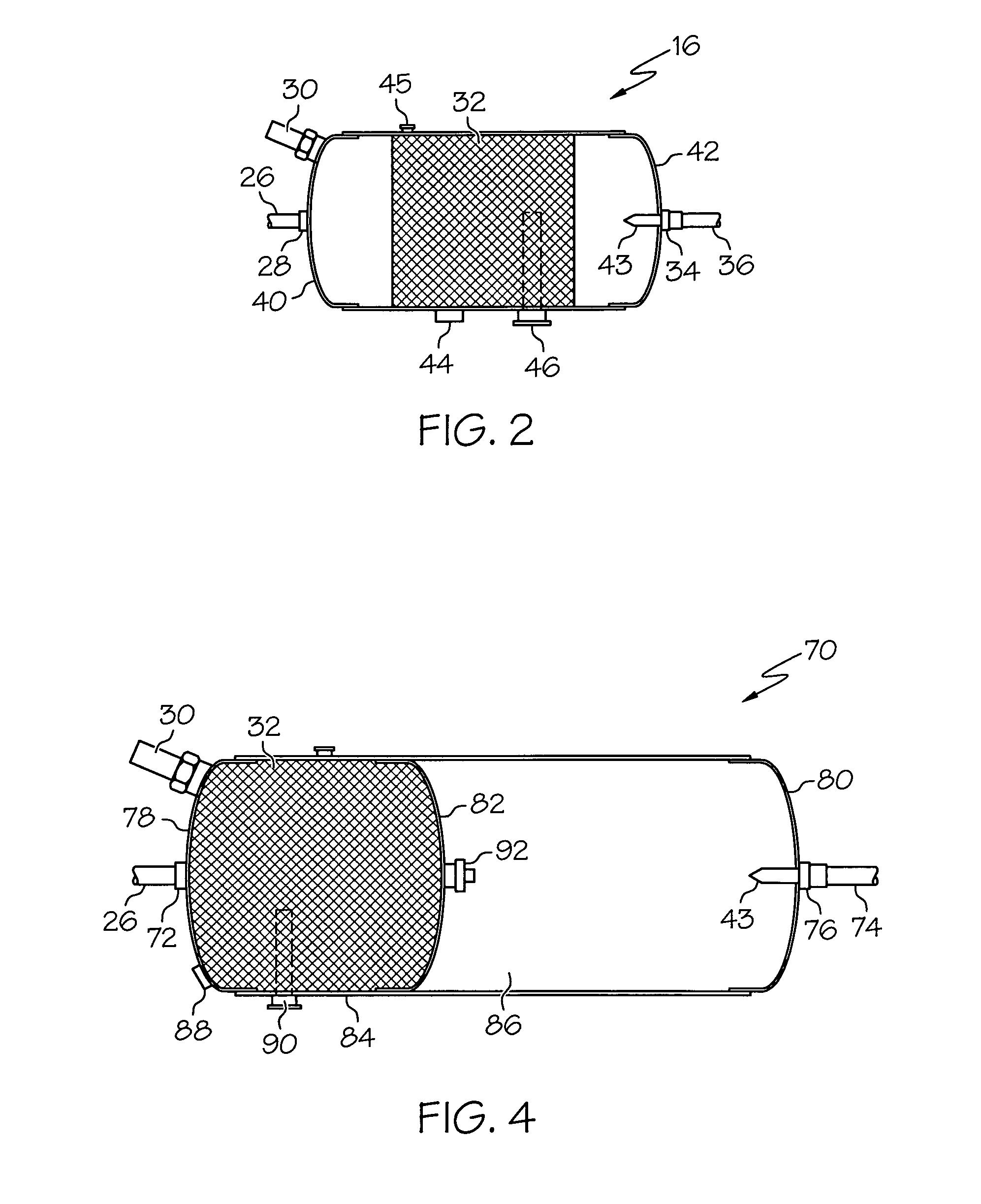
[0005]The present invention is directed to an improved vapor droplet removal apparatus for a motor vehicle compressed air storage system in which potentially moisture-laden air supplied to a canister by an oil-lubricated compressor is passed through a mist-eliminating mesh that removes moisture and oil mist in the air. The mesh coalesces droplets of both water vapor and oil vapor in the air stream, and is not contaminated by either. The coalesced moisture and oil are collected in a sump area of the canister, and are periodically exhausted through an electrically activated drain. The drain may be a gravity drain installed in the sump area, but is preferably a siphon drain installed in a dry portion of the canister. The canister may be a stand-alone device through which compressed air is delivered to a separate pressure tank, or may be integrated into a pressure tank for space efficiency.

Problems solved by technology

Since excessive ambient moisture in the compressed air can be harmful to air brakes and other pneumatically activated devices, most compressed air storage systems include a moisture removal mechanism.
However, the problem with this approach is that air supplied by an oil-lubricated compressor invariably contains a certain amount of blow-by oil mist that contaminates the desiccant material so that it will no longer adsorb moisture or regenerate.

Method used


Image

  • Water and oil mist elimination apparatus for a vehicular compressed air storage system
  • Water and oil mist elimination apparatus for a vehicular compressed air storage system
  • Water and oil mist elimination apparatus for a vehicular compressed air storage system

Examples


Embodiment Construction

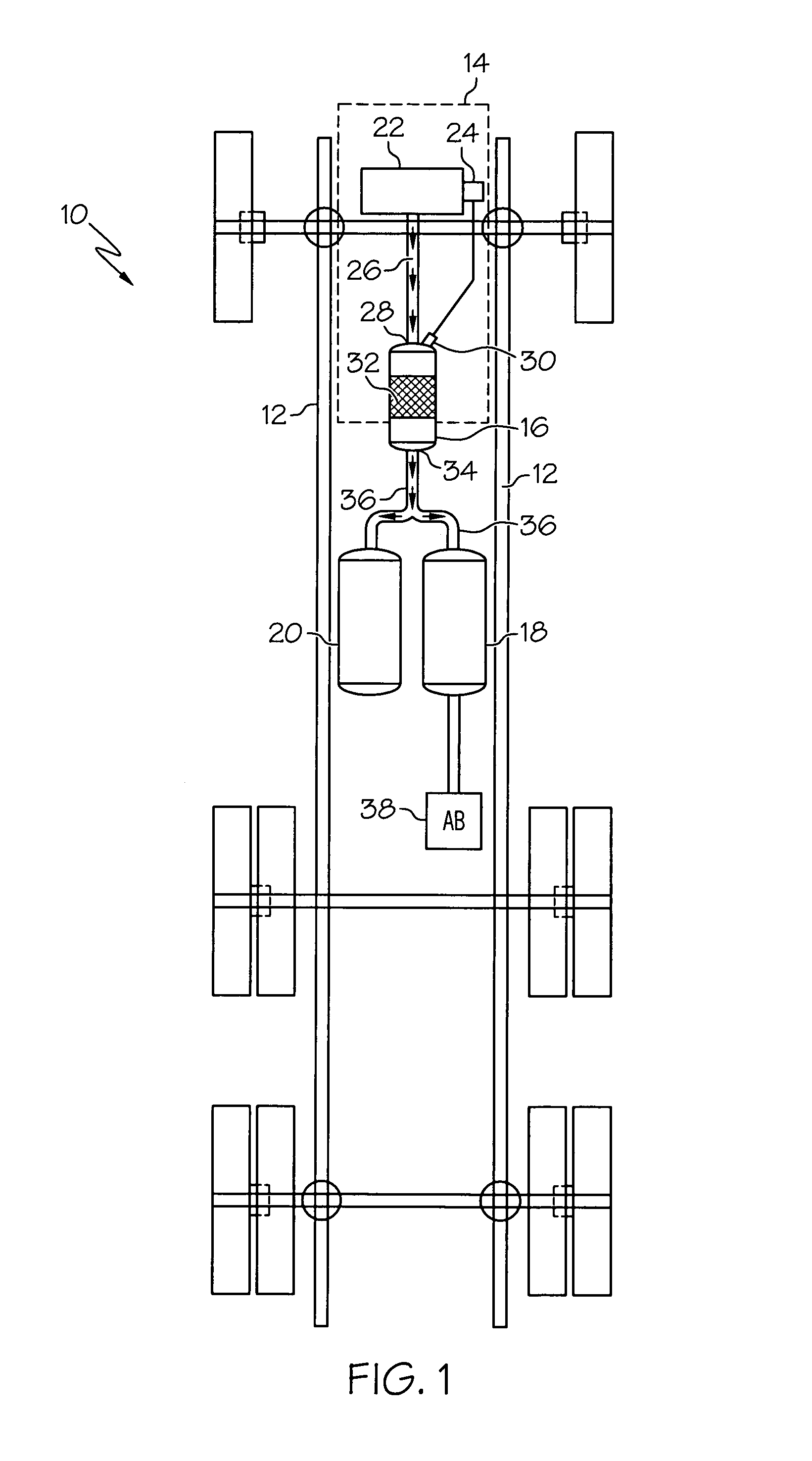
[0012]Referring to FIG. 1, the reference numeral 10 generally designates a commercial truck such as a semi-tractor. The frame 12 of the tractor 10 supports the powertrain 14 and various air storage system canisters 16-20. The air storage system includes a compressor 22, a stand-alone mist elimination canister 16, a primary air storage tank 18, and a secondary air storage tank 20. In a typical application, the compressor 22 is an engine-driven component, and includes a pneumatically operated unloading or bypass device 24 for controlling the compressor load to regulate the air pressure in one or more of the canisters 16-20. Alternately, the compressor 22 may be driven an electric or hydraulic motor with a speed or on / off control for controlling the compressor load.

[0013]In the embodiment of FIG. 1, the air hose 26 couples the output of compressor 22 to the inlet 28 of a mist elimination canister 16. A governor 30 responsive to the pressure in canister 16 is coupled to the compressor-u...


PUM

PropertyMeasurementUnit
areaaaaaaaaaaa
pressureaaaaaaaaaa
air pressureaaaaaaaaaa

Abstract

A moisture removal apparatus for a vehicular compressed air storage system includes a canister of mist-eliminating mesh that collects moisture and oil droplets in the air and exhausts them through a gravity drain. The mesh coalesces droplets of both water and oil vapor in the air stream, and is not contaminated by either. The mist eliminating canister can be a stand-alone device through which compressed air is delivered to a pressure tank, or may be integrated into a pressure tank for space efficiency.

Description

RELATED APPLICATIONS[0001]This application claims the benefit of provisional U.S. Patent Application Ser. No. 61 / 007,567, filed Dec. 13, 2007.TECHNICAL FIELD[0002]The present invention relates to a vehicular compressed air storage system, for operating air brakes for example, and more particularly to an apparatus for removing excessive moisture from the stored air.BACKGROUND OF THE INVENTION[0003]Commercial vehicles are commonly equipped with a compressed air storage system for operating air brakes and other pneumatically activated devices. An air compressor driven by the vehicle engine supplies compressed air to one or more storage vessels, which in turn are coupled to the air brakes and other pneumatically activated devices. Since excessive ambient moisture in the compressed air can be harmful to air brakes and other pneumatically activated devices, most compressed air storage systems include a moisture removal mechanism.[0004]One of the most common and cost effective ways to remo...

Claims


Application Information

Patent Timeline
Patent Type & Authority Patents(United States)
IPC IPC(8): B01D50/00
CPCB01D45/08B01D46/10B01D50/002B60T17/004Y10S55/17B01D50/20
Inventor JOHNSON, TRUMAN G.
Owner JOHNSON WELDED PRODS
Learn More